Image forming apparatus

Active Publication Date: 2010-12-30
CANON KK
View PDF15 Cites 13 Cited by
  • Summary
  • Abstract
  • Description
  • Claims
  • Application Information

AI Technical Summary

Benefits of technology

[0007]The present invention is directed to an image forming apparatus capable of improving operability during insert

Problems solved by technology

However, in conventional configuration in which locking and unlocking operations are performed by operating the operation lever, which is rotated around a rotation shaft parallel to the pullout direction, since locking operation is performed by rotating the operation lever af

Method used


Image

  • Image forming apparatus
  • Image forming apparatus
  • Image forming apparatus

Examples


Example

[0019]Various exemplary embodiments, features, and aspects of the invention will be described in detail below with reference to the drawings.

[0020]Dimensions, materials, and shapes, and arrangement thereof described in the exemplary embodiments below can be changed as appropriate according to configurations and various conditions of the apparatuses to which the present invention is applied, and it is not intended to limit scope of the present invention to these.

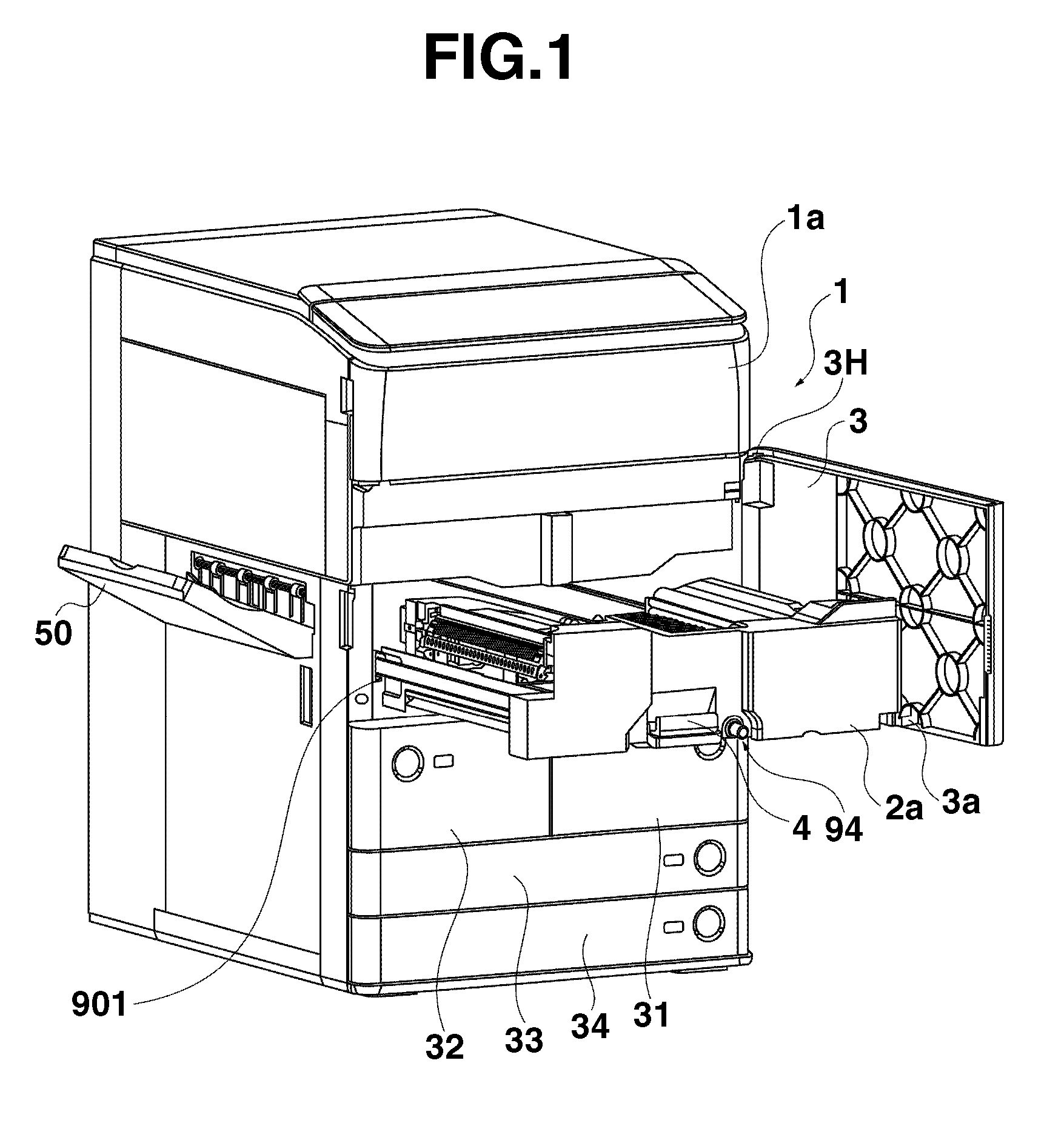
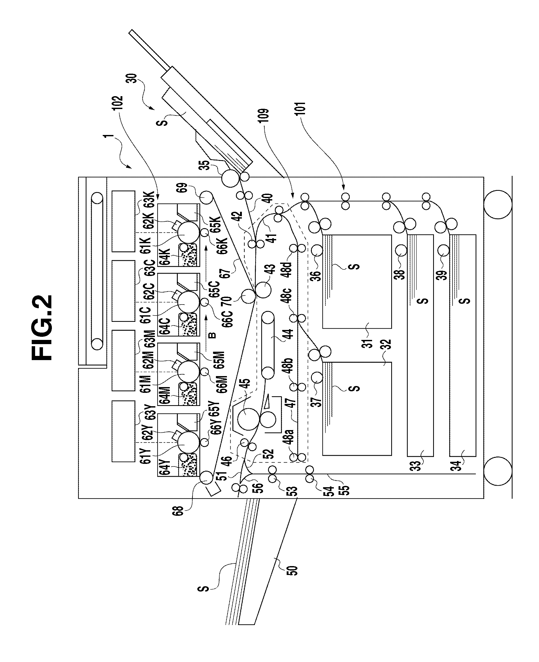
[0021]FIG. 1 is a perspective view of an image forming apparatus as an example according to the exemplary embodiment of the present invention. FIG. 2 is a schematic sectional view of the image forming apparatus as an example according to the exemplary embodiment of the present invention. The image forming apparatus is a color image forming apparatus employing an electrophotographic process. The image forming apparatus adopts an intermediate transfer tandem system in which 4 color image forming units are arranged side by side ...


PUM


Abstract

An image forming apparatus includes a cover configured to open/close with respect to an apparatus main body of the image forming apparatus, a pullout unit, a locking member configured to lock the pullout unit according to an operation of inserting the pullout unit into the apparatus main body, and an abutting member movable between a position where the abutting member regulates the closure of the cover by abutting against the cover and a position where the abutting member does not regulate the closure of the cover. When the locking member does not lock the pullout unit, the abutting member is positioned at the position where the abutting member regulates the closure of the cover.

Description

BACKGROUND OF THE INVENTION[0001]1. Field of the Invention[0002]The present invention relates to an image forming apparatus that forms an image on a paper sheet.[0003]2. Description of the Related Art[0004]Conventionally, as a pullout unit for integrally pulling out a transfer unit, a pre-fixing conveyance unit, a fixing unit, and a sheet conveyance unit such as a two-sided conveyance unit of an image forming apparatus, there is available a unit configured to pull out from an apparatus front side of an apparatus main body. The unit is used to perform, for example, handling of a paper sheet clogging (hereinafter, referred to as jam) in a sheet conveyance path provided in the pullout unit or maintenance of the apparatus, while the pullout unit is in a state of being pulled out from the apparatus main body.[0005]The pullout unit is provided with an operation lever that can be rotated around a rotation central axis parallel to a pullout direction. By rotating the operation lever, lockin...

Claims


Application Information

Patent Timeline
IPC IPC(8): G03G15/00
CPCG03G21/185G03G21/1647G03G21/1633G03G2221/1654
Inventor FUJITA, KEIKO
Owner CANON KK
Why Eureka
Try Eureka