Rotor blade with reduced rub loading

a rotor blade and load reduction technology, applied in the direction of liquid fuel engines, marine propulsion, vessel construction, etc., can solve the problems of excessive fan blade rubs and blade damage, and exert large load of rubs on rotating disks and bearings, and achieve the effect of facilitating reducing load

Active Publication Date: 2010-12-30
GENERAL ELECTRIC CO
View PDF21 Cites 23 Cited by
  • Summary
  • Abstract
  • Description
  • Claims
  • Application Information

AI Technical Summary

Benefits of technology

[0007]In another embodiment, an airfoil comprises a tip-rake located on at least a part of the tip portion extending between said first and second sidewalls, said tip-rake having a rake-profile that facilitates reducing loading induced to said airfoil during tip rubs.

Problems solved by technology

Under certain engine operating conditions, the rotor blades may be subject to blade tip rub events that induce radial and tangential loads in the blade airfoils.
Excessive rub loads may facilitate damage in the blade due to vibratory and fatigue conditions.
Excessive rub loads from the blade rubs may also facilitate secondary damage that includes damage to non-adjacent blades and the casing.
Excessive fan blade rubs may exert large rub loads on the rotating disks and bearings if the blade plows through the fan case abradable system.

Method used


Image

  • Rotor blade with reduced rub loading
  • Rotor blade with reduced rub loading
  • Rotor blade with reduced rub loading

Examples


Embodiment Construction

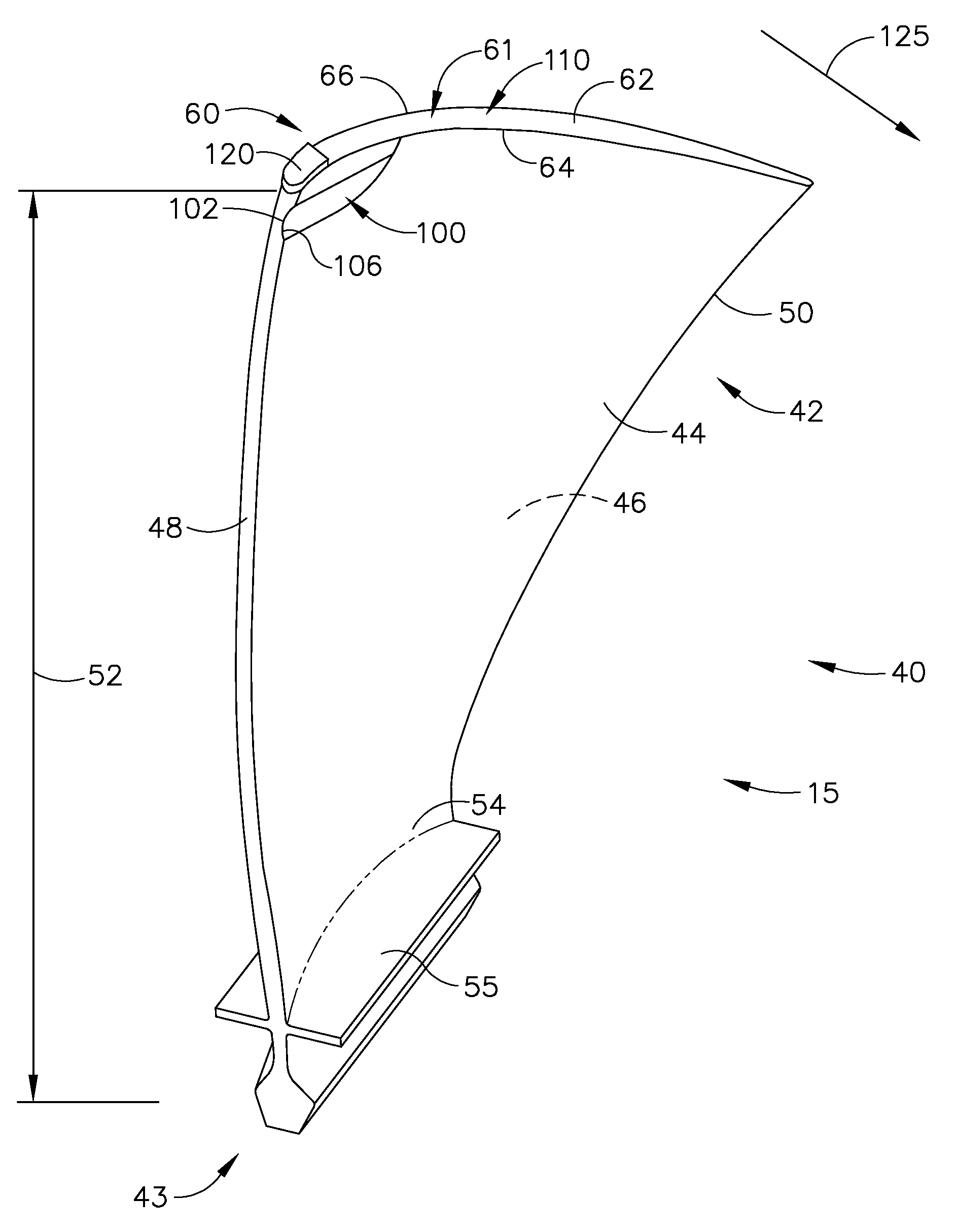
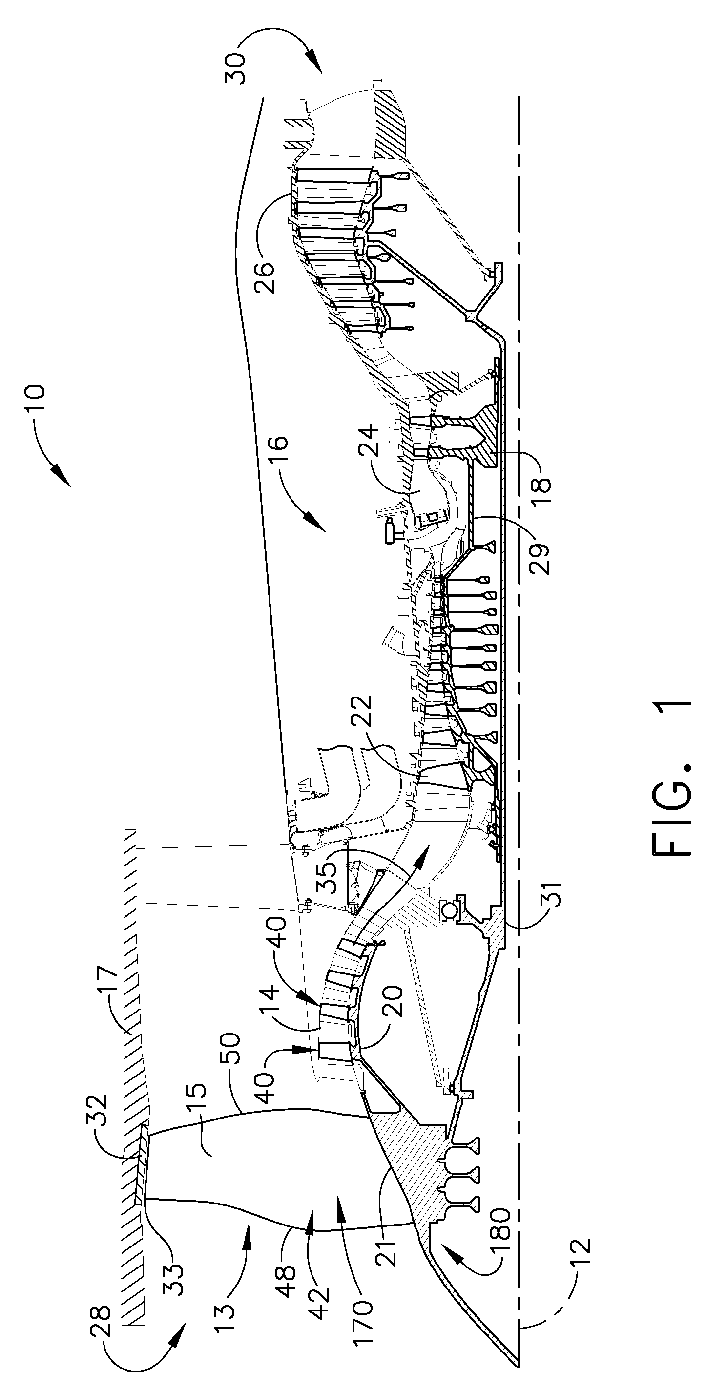
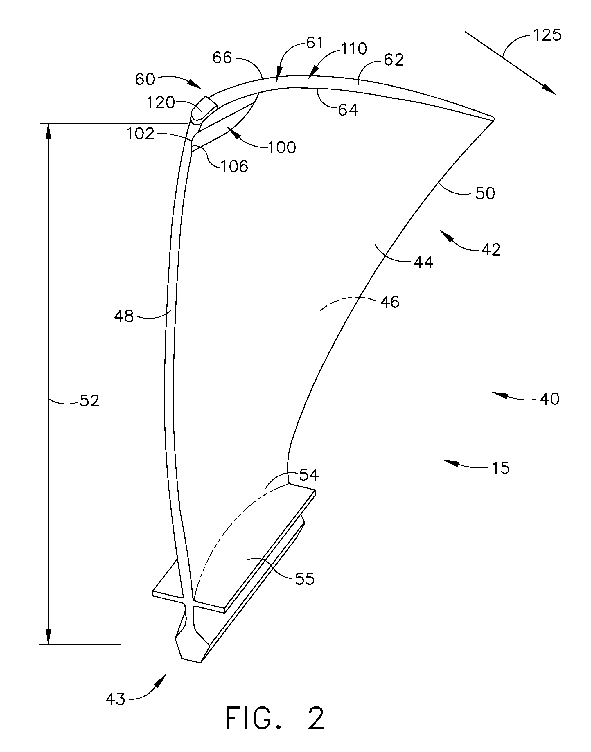
[0018]FIG. 1 is a schematic illustration of an exemplary engine assembly 10 having an exemplary embodiment of the present invention of a rotor blade 15 having a tip portion 60 that facilitates reducing rub loads induced to the rotor blade 15 when a tip rub occurs between the blade tip and the casing 17. Engine assembly 10, having a longitudinal axis 12, comprises a fan assembly 13, a booster compressor 14, a core gas turbine engine 16, and a low-pressure turbine 26 that is coupled with fan assembly 13 and booster compressor 14. Core gas turbine engine 16 includes a high-pressure compressor 22, a combustor 24, and a high-pressure turbine 18. Booster compressor 14 includes a plurality of rotor blades40 that extend substantially radially outward from a rotor disk 20 coupled to a first drive shaft 31. Engine assembly 10 has an intake side 28 and an exhaust side 30. Compressor 22 and high-pressure turbine 18 are coupled together by a second drive shaft 29.

[0019]During operation, air ente...


PUM


Abstract

An airfoil for use in a rotor assembly is disclosed, the airfoil having a tip-cutter located on a sidewall near a tip portion, wherein the tip-cutter is capable of removing a portion of an abradable material during a tip rub. In another embodiment, an airfoil has a tip-grinder located on the tip portion, wherein the tip-grinder capable of removing a portion of an abradable material during a tip rub. In another embodiment, an airfoil has a tip-rake that facilitates reducing loading induced to said airfoil during tip rubs.

Description

BACKGROUND OF THE INVENTION[0001]This invention relates generally to gas turbine engines, and more specifically to methods and apparatus to reduce tip nib loads induced in rotor blades.[0002]At least some known gas turbine engines typically include a casing, a fan rotor assembly, low and high pressure compressors, a combustor, and at least one turbine. The compressors compress air which is channeled to the combustor where it is mixed with fuel. The mixture is then ignited for generating hot combustion gases. The combustion gases are channeled to the turbine(s) which extracts energy from the combustion gases for powering the compressor(s), as well as producing useful work to propel an aircraft in flight or to power a load, such as an electrical generator.[0003]Some known fan and compressor assemblies include a casing that encloses a rotor having a plurality of rotor blades. Under certain engine operating conditions, the rotor blades may be subject to blade tip rub events that induce ...

Claims


Application Information

Patent Timeline
Patent Type & Authority Applications(United States)
IPC IPC(8): F01D5/14F01D5/28
CPCF01D5/20F05D2220/36Y02T50/672F01D11/122F04D29/324F05D2240/303F05D2240/307Y02T50/60
Inventor KRAY, NICHOLAS JOSEPHCRALL, DAVID W.MOLLMANN, DANIEL E.GARDNER, DONALD LEEJOHNSON, MARCIA BOYLEWEAVER, HAWARD P.FARSON, MAX ROBERT
Owner GENERAL ELECTRIC CO
Why Eureka
Try Eureka