Antenna of portable electronic devices

a portable electronic device and antenna technology, applied in the direction of loop antennas, antenna supports/mountings, antenna structure forms, etc., can solve the problems of small antennas used in portable electronic devices, adversely affecting the communication quality of portable electronic devices,

Active Publication Date: 2011-01-06
CHI MEI COMM SYST INC
View PDF10 Cites 30 Cited by
  • Summary
  • Abstract
  • Description
  • Claims
  • Application Information

AI Technical Summary

Problems solved by technology

Generally, antennas used in the portable electronic devices are very small due to the small size of the portable electronic devices.
As a result, communication quality of the portable electronic devices may be adversely affected.

Method used


Image

  • Antenna of portable electronic devices
  • Antenna of portable electronic devices
  • Antenna of portable electronic devices

Examples


Embodiment Construction

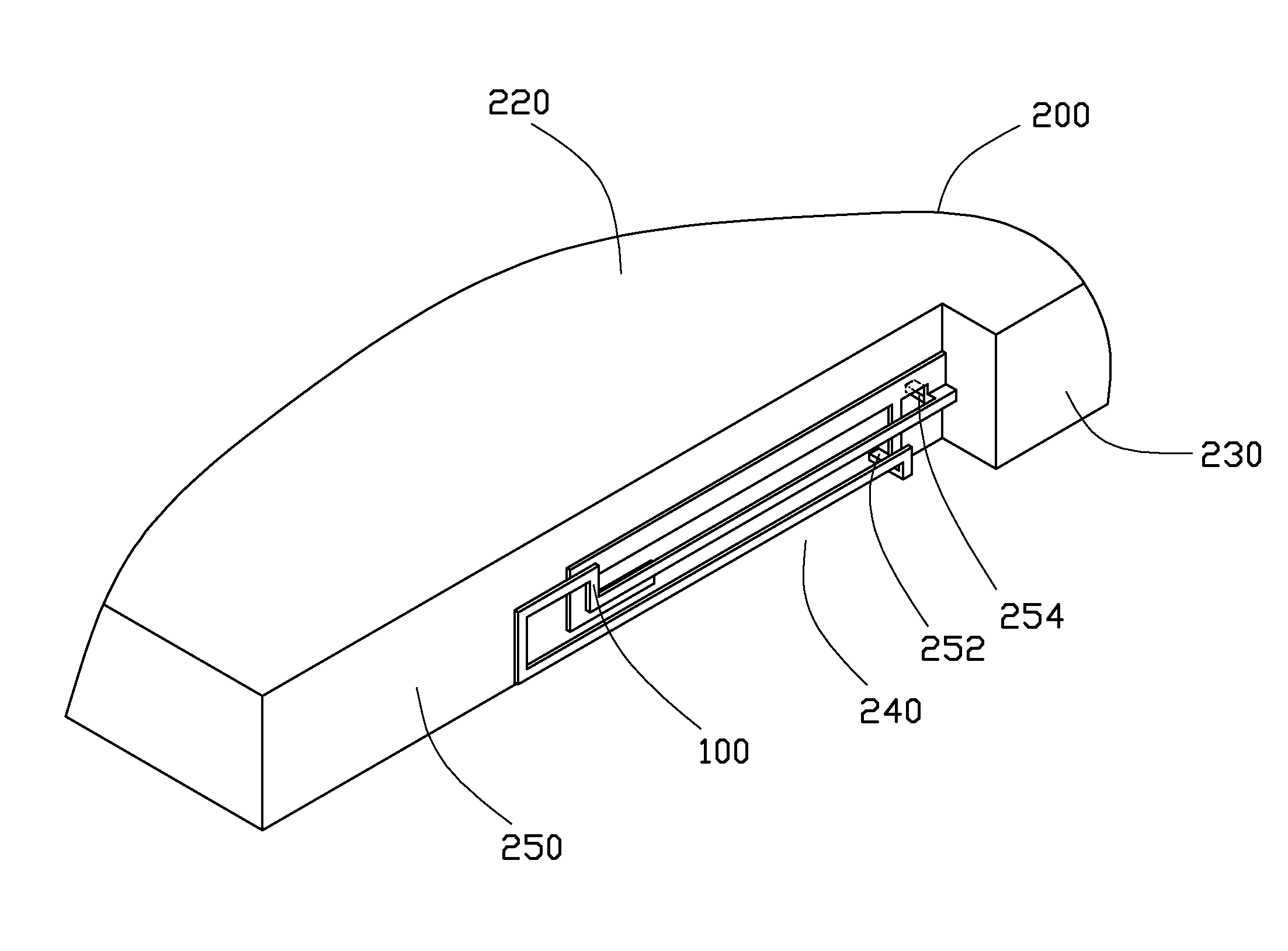
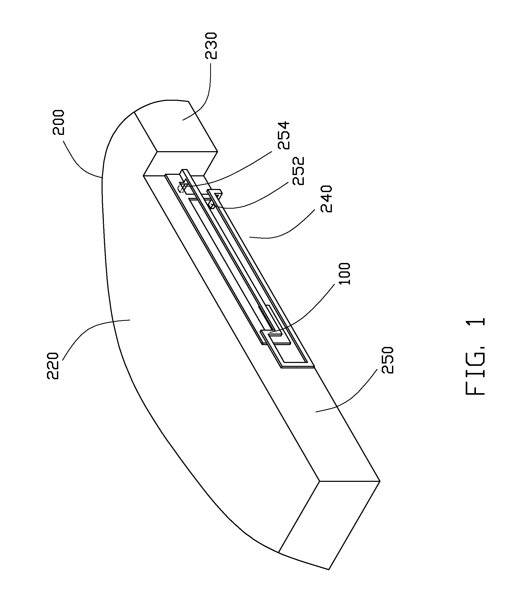
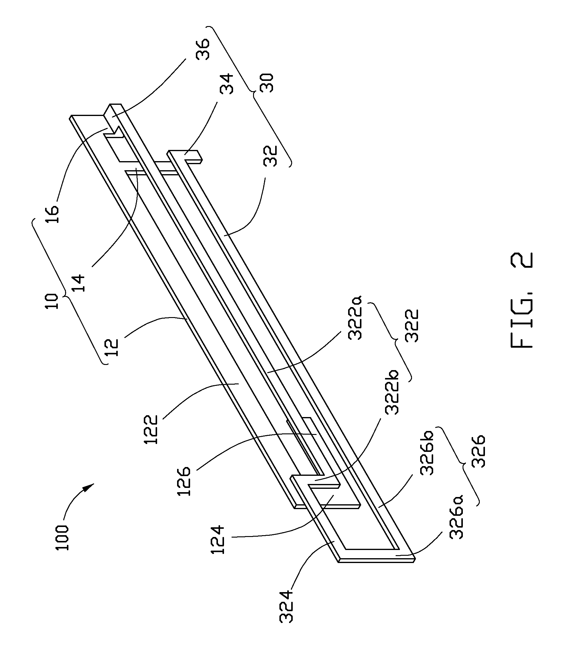
[0010]FIG. 1 and FIG. 2 schematically show an antenna 100 according to an exemplary embodiment, for use in portable electronic devices. The antenna 100 can be installed in a portable electronic device and connected to a conventional circuit board 200 of the portable electronic device to receive / send wireless signals when the portable electronic device is used in wireless communications.

[0011]The circuit board 200 includes a flat main surface 220 and a flat side surface 230 perpendicularly connected to the main surface 220. One end of the side surface 230 includes a recess, which forms a receiving portion 240. The receiving portion 240 includes a flat assembly surface 250 parallel to the side surface 240. A grounding connector 252 and a feed connector 254 are mounted on the assembly surface 250 and electrically connected to the circuit board 200.

[0012]The antenna 100 is made of conductive materials and includes a first antenna unit 10 and a second antenna unit 30.

[0013]The first ante...


PUM


Abstract

An antenna used in portable electronic devices includes a first antenna unit shaped as a planar inverted-F antenna (PIFA) and a second antenna unit shaped as a loop antenna and connected to the first antenna unit. The first antenna unit receives / sends wireless signals at relatively higher frequencies, the second antenna unit receives / sends wireless signals at relatively lower frequencies, and the first antenna unit is coupled with the second antenna unit to regulate the working frequency band of the antenna.

Description

BACKGROUND[0001]1. Technical Field[0002]The present disclosure relates to antennas, and particularly to an antenna used in portable electronic devices.[0003]2. Description of Related Art[0004]Generally, antennas used in the portable electronic devices are very small due to the small size of the portable electronic devices. When working conditions of the portable electronic devices (e.g., ambient temperatures, humidity, and taken / placed manners) changes, working characteristics of these antennas are easily influenced because of their sizes. Thus, frequency offset of the antennas may occur, i.e., the frequencies of wireless signals that can be transferred by the antennas may change. As a result, communication quality of the portable electronic devices may be adversely affected.[0005]Therefore, there is room for improvement within the art.BRIEF DESCRIPTION OF THE DRAWINGS[0006]Many aspects of the present antenna can be better understood with reference to the following drawings. The com...

Claims


Application Information

Patent Timeline
Patent Type & Authority Applications(United States)
IPC IPC(8): H01Q1/36H01Q21/00H01Q5/10
CPCH01Q1/243H01Q5/40H01Q9/0421H01Q7/00
Inventor LEE, YI-CHIEH
Owner CHI MEI COMM SYST INC
Why Eureka
Try Eureka