Transmission module for pneumatic tool

Inactive Publication Date: 2011-01-13
HYPHONE MASCH IND CO LTD
View PDF13 Cites 6 Cited by
  • Summary
  • Abstract
  • Description
  • Claims
  • Application Information

AI Technical Summary

Benefits of technology

[0006]The main object of the present invention is to provide a tra

Problems solved by technology

The transmission module of TW M356577 is complica

Method used


Image

  • Transmission module for pneumatic tool
  • Transmission module for pneumatic tool
  • Transmission module for pneumatic tool

Examples


Example

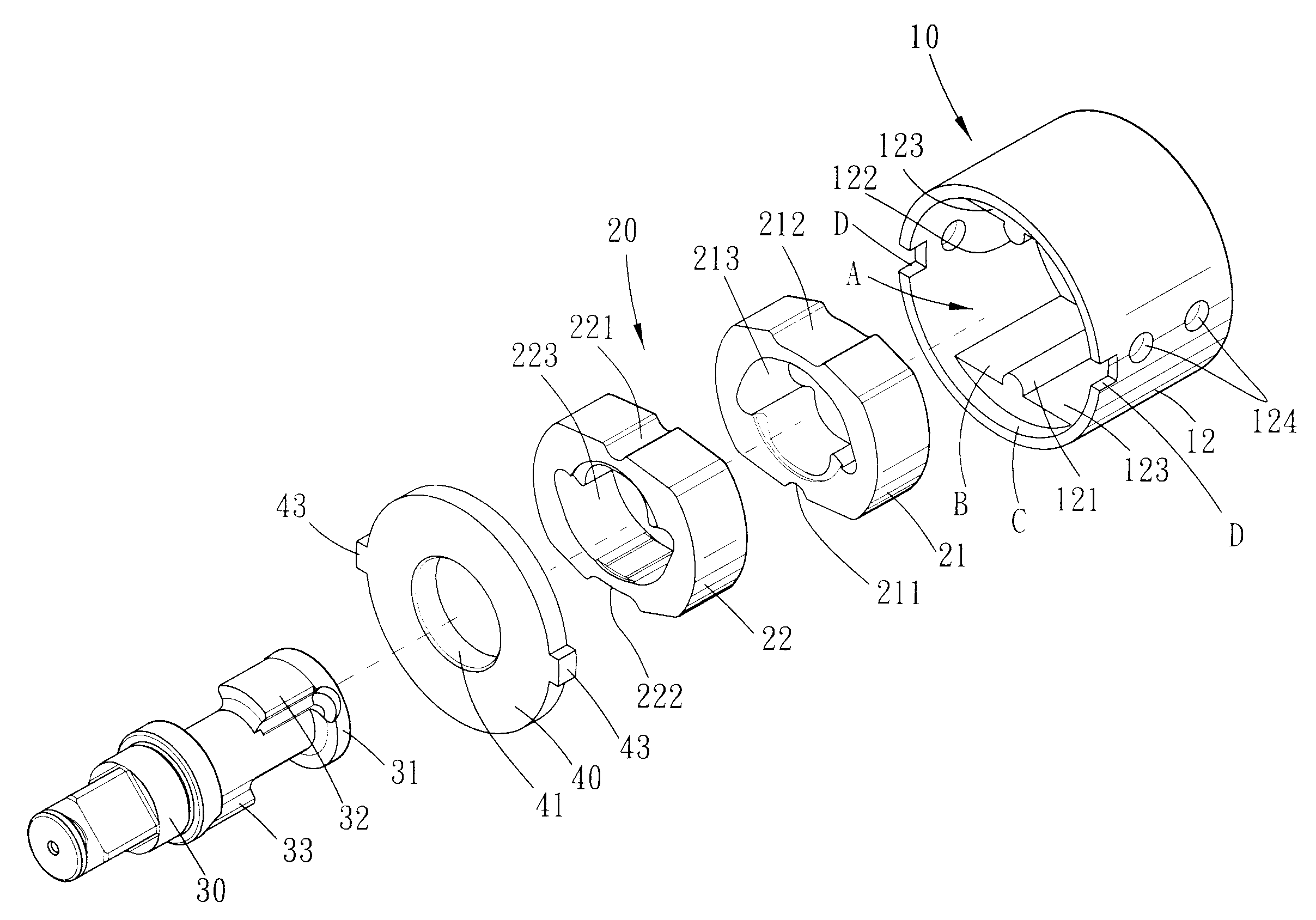
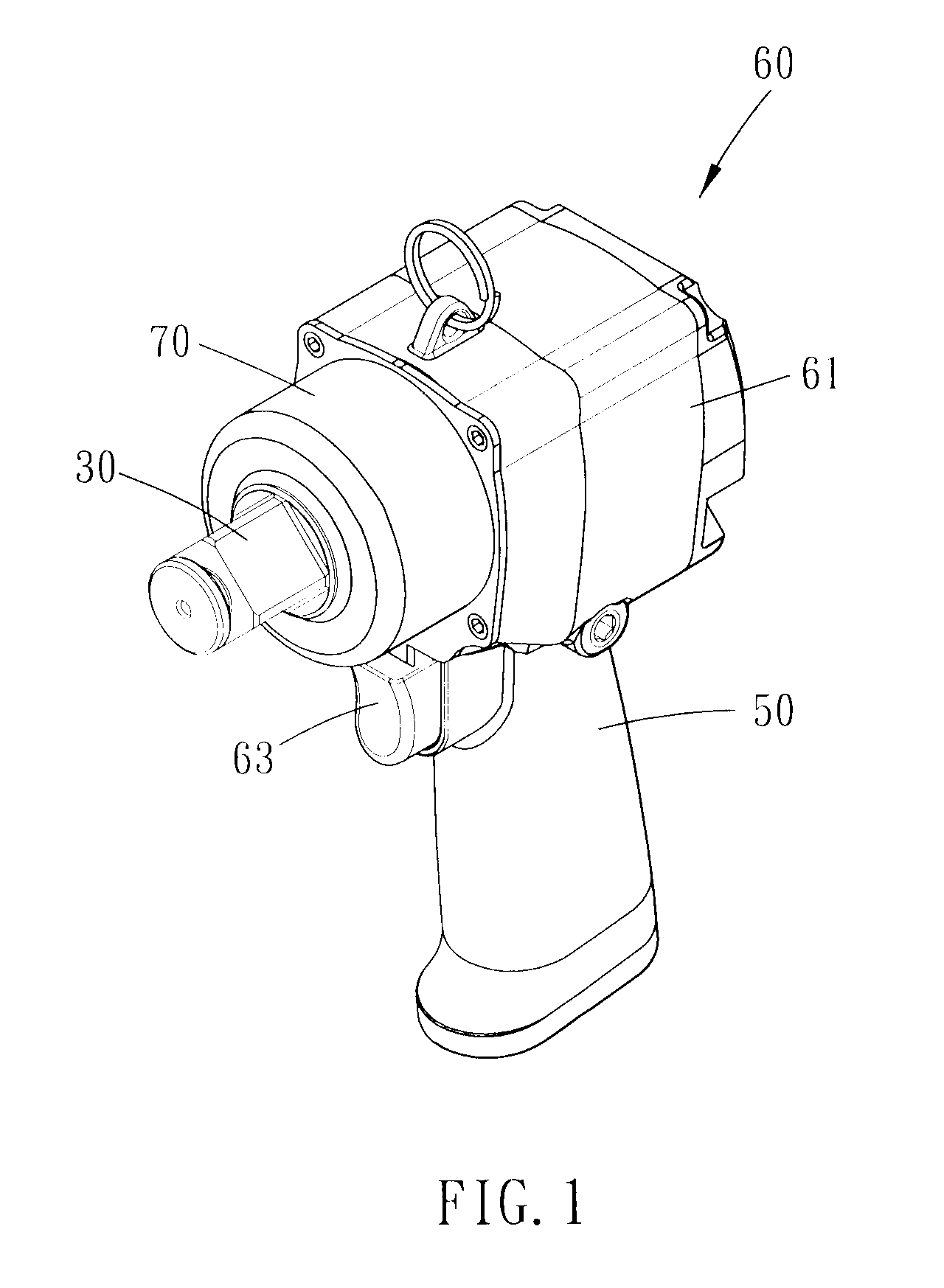
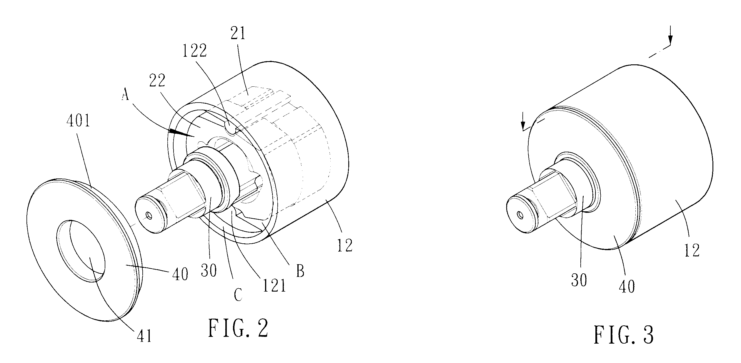
[0020]Please refer to FIG. 1. The transmission module of the present invention can be installed on a pneumatic tool. Please refer to FIG. 2 to FIG. 5. The transmission module includes a sleeve member 10, a hammering portion 20, an axle 30 and a cover disc 40. The sleeve member 10 has a rear disc 11 and a cylinder body 12. A receiving space A is defined between the rear disc 11 and the cylinder body 12, and the receiving space A has an open end. The rear disc 11 is formed with a teethed bore 111 for a teethed axle of a motor to engage therewith, so that the sleeve member 10 and the teethed axle of the motor are in a rotational operative relationship. The cylinder body 12 is axially extended form the rear disc 11 and has an inner surface and an outer surface. The inner surface of the cylinder body 12 is formed with two opposite plane stages B. A distance C is defined between the plane stages B and the open end of the receiving space A. The inner surface of the cylinder body 12 is furt...


PUM

PropertyMeasurementUnit
Thicknessaaaaaaaaaa
Diameteraaaaaaaaaa

Abstract

A transmission module includes a sleeve member, a cover disc, a hammering portion and an axle. The sleeve member has a rear disc and a cylinder body. A receiving space is defined between the rear disc and the cylinder body. The rear disc is formed with a teethed bore. The inner surface of the cylinder body is formed with at least one axially-stretched rib. The cover disc is disposed on the open end of the receiving space. The cover disc is formed with an axial bore. The hammering portion includes at least one rotary hammer, which is received in the receiving space. The rotary hammer has a through hole and a positioning groove. The rib is engaged with the positioning groove. The axle has a driven end and a working end. The driven end is inserted through the axial bore and mated with the through hole.

Description

BACKGROUND OF THE INVENTION[0001]1. Field of the Invention[0002]The present invention relates to a transmission module for a pneumatic tool.[0003]2. Description of the Prior Art[0004]Some conventional pneumatic tools are provided to tightly thread a screw in or out off a threaded bore. The pneumatic tool includes a transmission module, such as disclosed in TW M356577, to rotate the screw. The transmission module of TW M356577 is complicated and takes a considerable time for assembling.[0005]The present invention is, therefore, arisen to obviate or at least mitigate the above mentioned disadvantages.SUMMARY OF THE INVENTION[0006]The main object of the present invention is to provide a transmission module which is simplified and can be assembled quickly.[0007]To achieve the above and other objects, a transmission module of the present invention includes a sleeve member, a cover disc, a hammering portion and an axle. The sleeve member has a rear disc and a cylinder body axially extende...

Claims


Application Information

Patent Timeline
IPC IPC(8): B25D9/06
CPCB25B21/026
Inventor CHEN, HSIEN CHUNG
Owner HYPHONE MASCH IND CO LTD
Why Eureka
Try Eureka