Single multi-chip lamp sources and related methods

Active Publication Date: 2011-01-13
IDEAL IND LIGHTING LLC
View PDF19 Cites 6 Cited by
  • Summary
  • Abstract
  • Description
  • Claims
  • Application Information

AI Technical Summary

Problems solved by technology

LED packages provide a challenge in effecting the different color beams needed for these various applications.
This configuration of multiple lamps does not approach the brightness needs or reflector efficiency required for these lighting units.
Also, the use of multiple lamps is limited by size constraints of the lighting unit such that the lamps are off-centered, leading to beam shifting.

Method used


Image

  • Single multi-chip lamp sources and related methods
  • Single multi-chip lamp sources and related methods
  • Single multi-chip lamp sources and related methods

Examples


Embodiment Construction

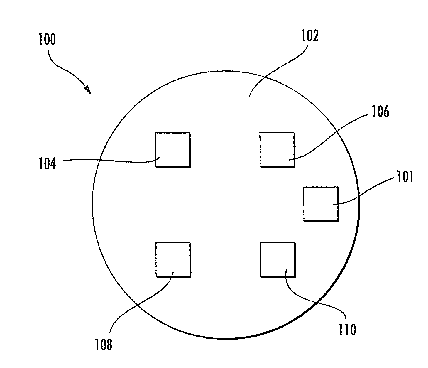
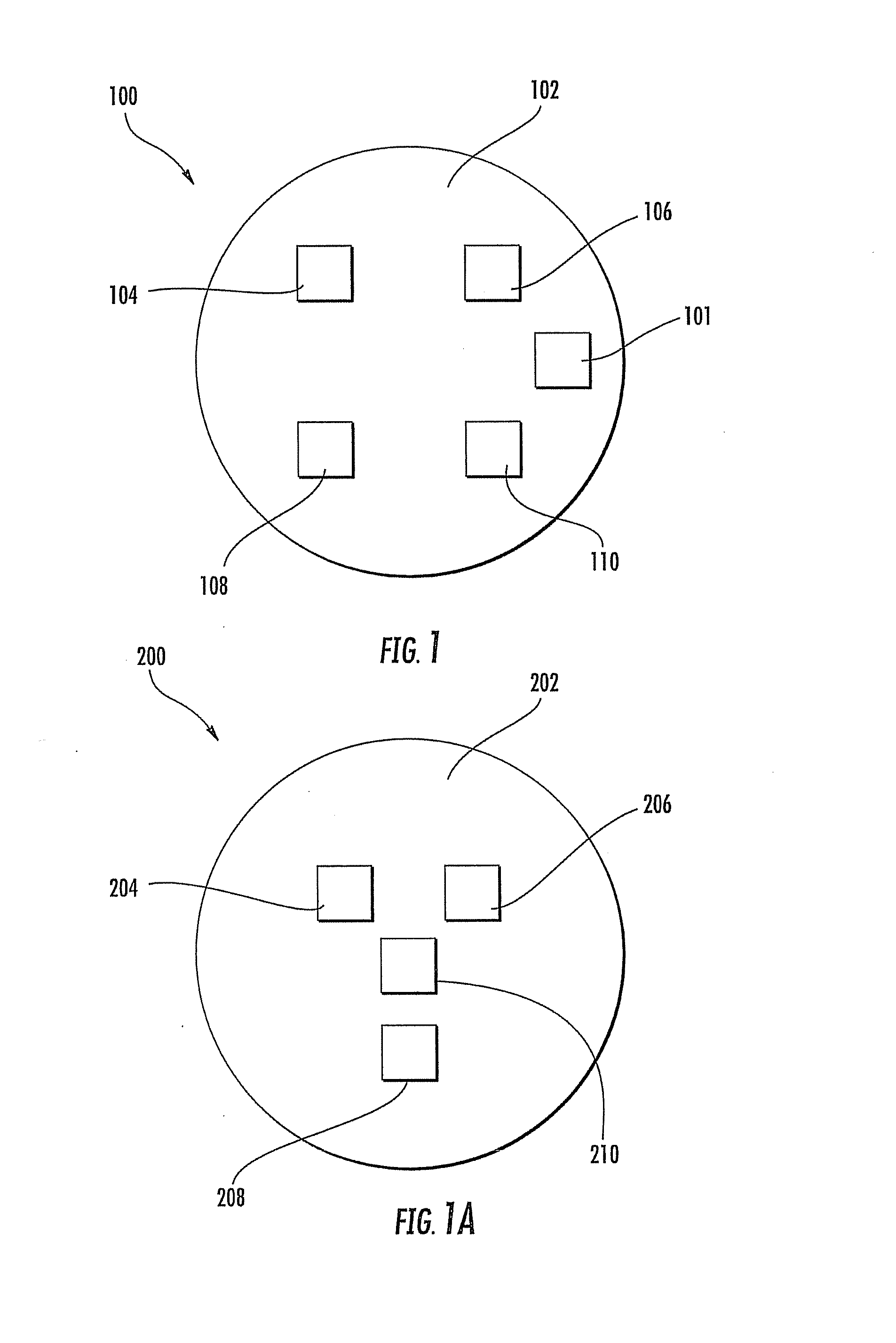
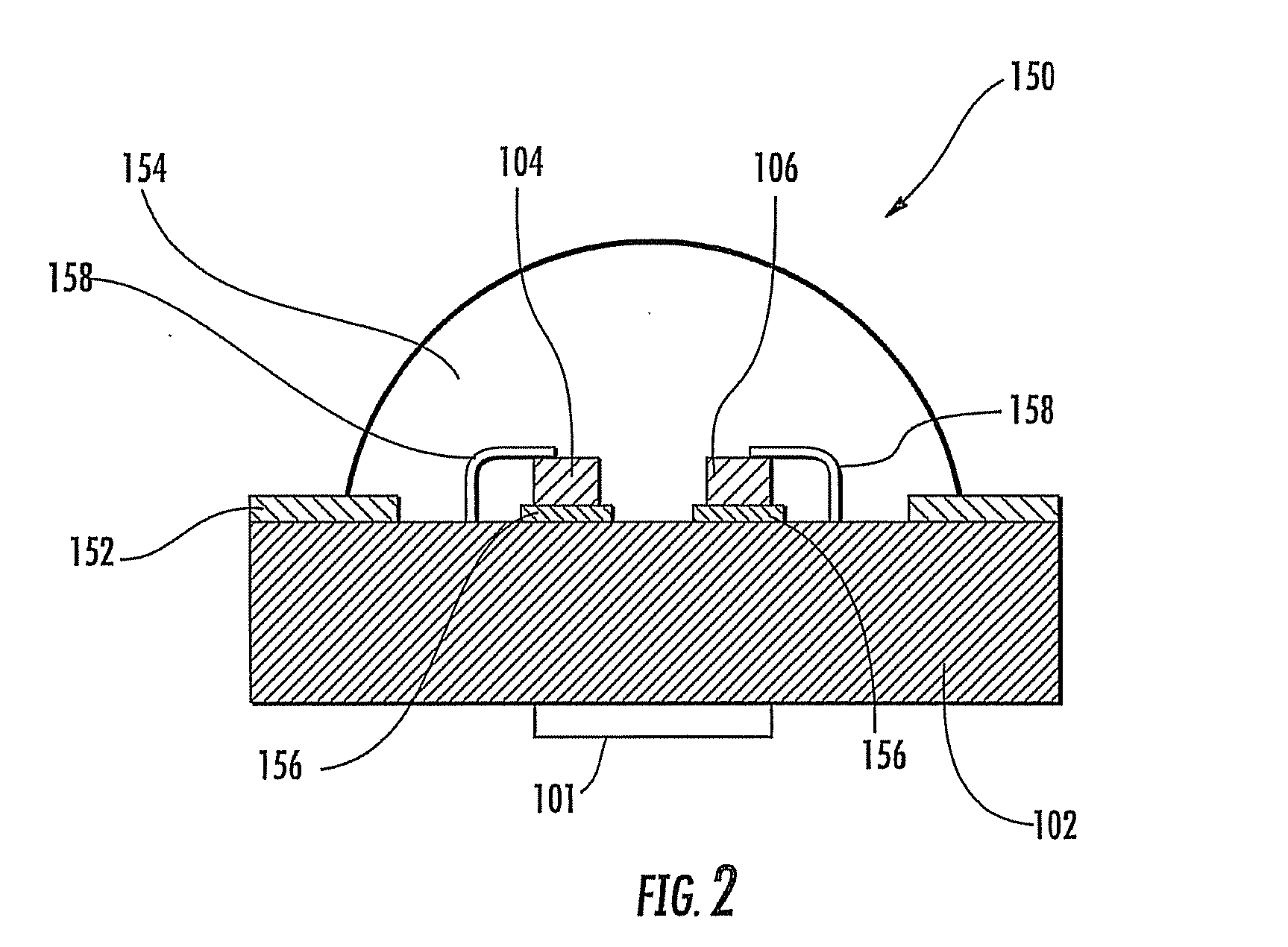
Light emitting device multi-chip lighting units and related methods are described herein with reference to FIGS. 1-4. As illustrated in FIGS. 1-4, some sizes of structures or portions may be exaggerated relative to other structures or portions for illustrative purposes and, thus, are provided to illustrate the general structures of the subject matter disclosed herein. Further, various aspects of the subject matter disclosed herein are described with reference to a structure or a portion being formed on other structures, portions, or both. As will be appreciated by those of skill in the art, references to a structure being formed “on” or “above” another structure or portions contemplates that additional structure, portion, or both may intervene. References to a structure or a portion being formed “on” another structure or portion without an intervening structure or portion are described herein as being formed “directly on” the structure or portion.

Furthermore, relative terms such as ...


PUM


Abstract

Multi-chip sources and related methods are disclosed. A single multi-chip lamp source can include a substrate and at least three light emitting diode (LED) chips operably configured to the substrate to form a single LED package. The LED chips can include at least three different colored LED chips. The LED chips can be configured to be actuatable either individually or together to provide selectable colored light beams. The LED chips can be positioned on the substrate such that an emitted light beam remains concentric without shifting regardless of the chip or chips emitting the light beam.

Description

TECHNICAL FIELDThe subject matter described herein relates to semiconductor light emitting devices. More particularly, the subject matter described herein relates to multiple light emitting device chips configured to a single substrate that can be housed in a lighting unit and related methods.BACKGROUNDSemiconductor light emitting devices, such as a light emitting diode (LED), may be provided in a package for protection, color selection, focusing, and the like for light emitted by the device. An LED package generally includes a substrate member on which an LED is mounted. The LED may include a mounting pad attached to the substrate member with electrical connections being made to the LED for applying an electrical bias. LEDs generally comprise an active region of semiconductor material sandwiched between two oppositely doped layers. When a bias is applied across the doped layers, holes and electrons are injected into the active region where they recombine to generate light. Light is...

Claims


Application Information

Patent Timeline
IPC IPC(8): H01L33/08H01L33/58
CPCF21K9/00F21L4/027F21Y2101/02H01L25/0753H01L2224/48471F21V29/20H01L2224/73265H01L2924/10253H01L2224/49175H01L2924/00H01L2924/181F21Y2115/10F21V29/70H01L2924/00012
Inventor MCMILLAN, MICHAEL
Owner IDEAL IND LIGHTING LLC
Why Eureka
Try Eureka