Electronic device and semi-auto sliding mechanism thereof

a technology of electronic devices and sliding mechanisms, which is applied in the direction of electrical apparatus casings/cabinets/drawers, instruments, etc., can solve the problem of difficult to achieve the miniaturization of electronic devices

Inactive Publication Date: 2011-01-13
HTC CORP
View PDF5 Cites 23 Cited by
  • Summary
  • Abstract
  • Description
  • Claims
  • Application Information

AI Technical Summary

Problems solved by technology

As the sliding hinge has considerable dimensions, miniaturization of the electronic device is not easy to achieve.

Method used


Image

  • Electronic device and semi-auto sliding mechanism thereof
  • Electronic device and semi-auto sliding mechanism thereof
  • Electronic device and semi-auto sliding mechanism thereof

Examples


Embodiment Construction

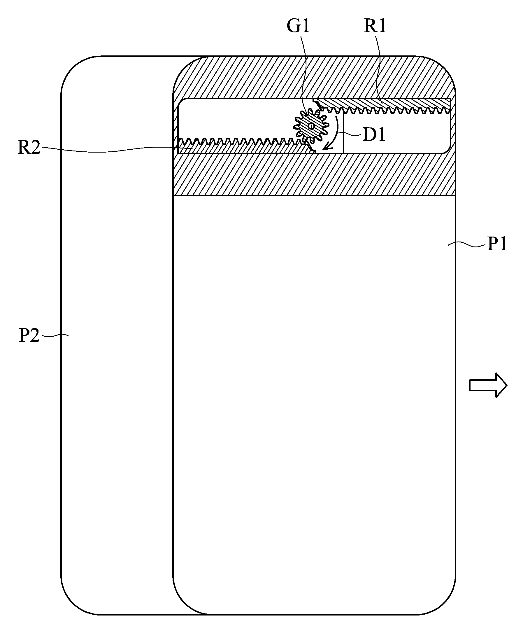
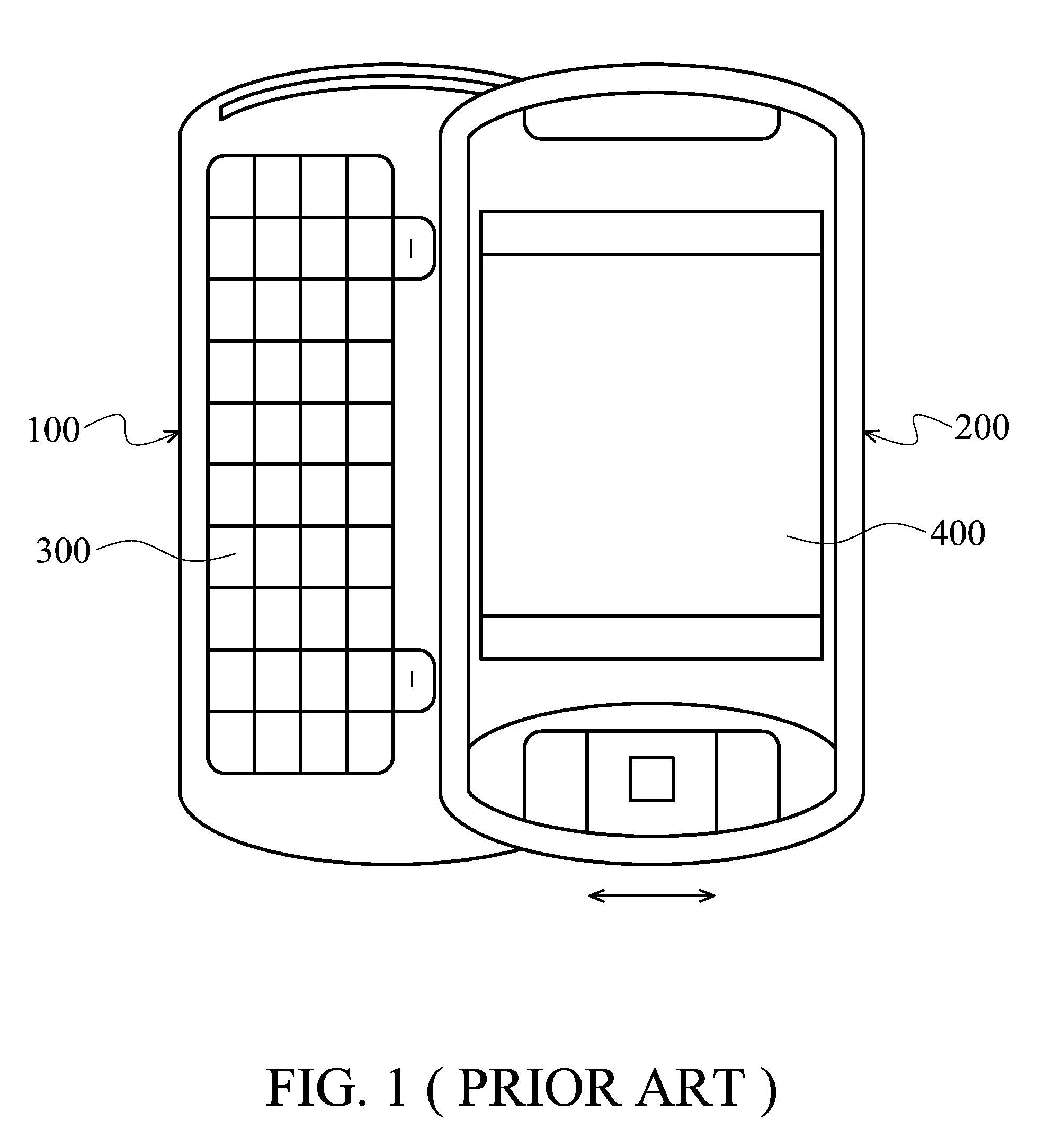
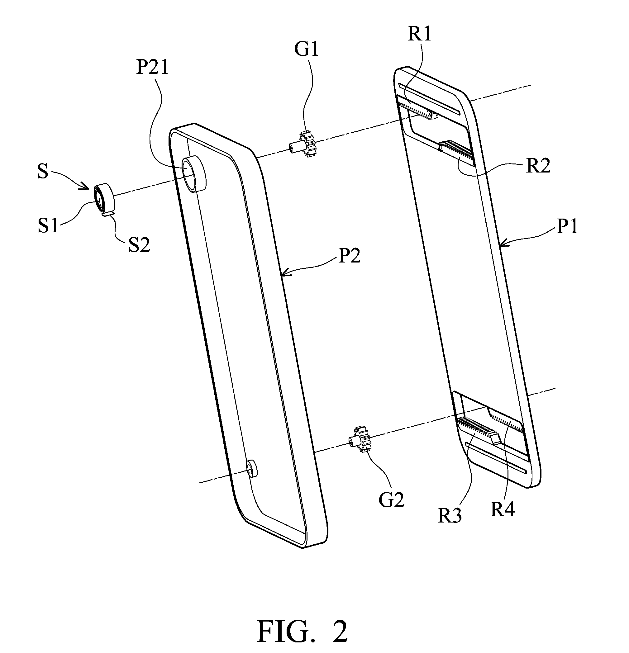
[0016]Referring to FIG. 2, an embodiment of a semi-auto sliding mechanism is disposed in an electronic device for connecting an input module and a display module thereof, such as the input module 100 and the display module 200 shown in FIG. 1. The semi-auto sliding mechanism primarily includes a first member P1, a second member P2, a first rack R1, a second rack R2, a pinion gear G1, and a clockwork spring S. In FIG. 2, the first and second racks R1 and R2 are mounted on the first member P1. The pinion gear G1 is pivotally connected to the second member P2 and can be rolled on the first rack R1 or the second rack R2. In this embodiment, the first and second racks R1 and R2 are parallel to each other and disposed on opposite sides of the pinion gear G1 for stably guiding the first member P1 to move relative to the second member P2. Similarly, a third rack R3, a fourth rack R4, and a pinion gear G2 corresponding to the first and second racks R1, R2 and the pinion gear G1 are disposed ...


PUM


Abstract

A semi-auto sliding mechanism is provided, including a first member, a second member, a first rack, a second rack, a pinion gear pivotally connected to the second member, and a clockwork spring connecting the pinion gear to the second member. The first and second racks are disposed on the first member. When the first member is moved relative to the second member to a first position by an external force, the pinion gear rolls along the first rack, and an elastic potential energy is stored in the clockwork spring. When the external force is released, the clockwork spring impels the pinion gear to rotate along the second rack, such that the first member moves relative to the second member from the first position to a second position.

Description

CROSS REFERENCE TO RELATED APPILCATIONS[0001]This Application claims priority of Taiwan Patent Application No. 098123182, filed on Jul. 9, 2009, the entirety of which is incorporated by reference herein.BACKGROUND OF THE INVENTION[0002]1. Field of the Invention[0003]This application relates in general to an electronic device and in particular to an electronic device having a semi-auto sliding mechanism.[0004]2. Description of the Related Art[0005]FIG. 1 depicts a conventional sliding-type electronic device, such as a mobile phone or PDA, including an input module 100 and a display module 200 reciprocally movable with respect to each other (as the arrows indicate in FIG. 1), wherein the input module 100 includes a keypad 300, and the display module 200 includes a screen 400.[0006]The input module 100 and the display module 200 are usually connected via a sliding hinge to facilitate semi-auto sliding therebetween. As the sliding hinge has considerable dimensions, miniaturization of th...

Claims


Application Information

Patent Timeline
Patent Type & Authority Applications(United States)
IPC IPC(8): H05K7/00F16H19/04
CPCY10T74/18088H04M1/0237
Inventor LIAO, YU-JINGYEH, YING-HAOCHENG, YING-YEN
Owner HTC CORP
Why Eureka
Try Eureka