Self-cleaning street lamp pole

A street light pole, self-cleaning technology, applied in cleaning methods and utensils, cleaning methods using tools, lighting devices, etc., can solve problems such as inconvenience

Active Publication Date: 2019-04-19
JIAGNSU PUYA LIGHTING TECH PUBLIC CO LTD
View PDF5 Cites 7 Cited by
  • Summary
  • Abstract
  • Description
  • Claims
  • Application Information

AI Technical Summary

Problems solved by technology

At present, because the street lamps are set on both sides of the road, the passing vehicles will cause dust, dust and sand, so that the dust and sand that fly will a

Method used


Image

  • Self-cleaning street lamp pole
  • Self-cleaning street lamp pole
  • Self-cleaning street lamp pole

Examples


Embodiment 1

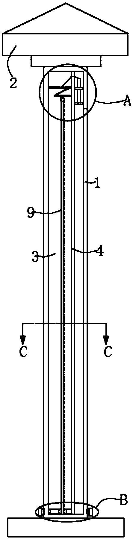
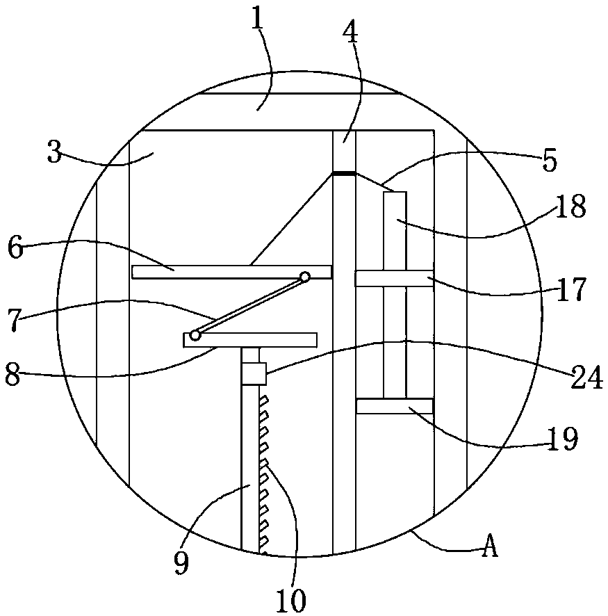
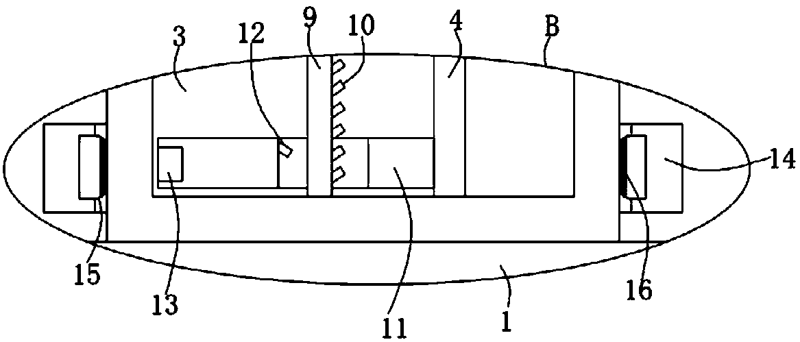
[0022] Reference Figure 1-4 , A self-cleaning street light pole, comprising a pole body 1, the top of the pole body 1 is fixedly connected with a lamp body 2, the pole body 1 is provided with a cavity 3, the inner side wall of the cavity 3 is fixedly connected with a U-shaped partition 4, the partition A drive mechanism is provided in the board 4, and the drive mechanism is connected with a control rope 5;

[0023] Further, the driving mechanism includes a fixed plate 17 fixedly connected to the partition 4 and the inner side wall of the cavity 3. The control rope 5 is fixedly connected with a sliding rod 18 at one end away from the sliding plate 6, and the bottom of the sliding rod 18 penetrates the fixed plate 17 and is fixed. Piston 19 is connected, and the piston 19 is in contact with the partition 4 and the inner wall of the cavity 3. When it is raining, the gas under the piston 19 becomes cold due to the washing of rain water, and the gas under the piston 19 becomes cold du...

Embodiment 2

[0031] Reference Figure 5-6 The difference between this embodiment and the first embodiment lies in the driving mechanism, that is, the driving mechanism includes a connecting plate 20, one end of the connecting plate 20 is fixedly connected to the top of the collecting frame 21, the bottom of the collecting frame 21 and the connecting plate 20 are both provided with For the water outlet, the end of the connecting plate 20 away from the collection frame 21 penetrates the rod body 1 and extends into the cavity 3. The connecting plate 20 is fixedly connected with an inserting rod 22, and the inner side wall of the partition 4 is fixedly connected to the inner side wall of the cavity 3. The position plate 23, the top of the plunger 22 penetrates the limit plate 23 and is fixedly connected to the control rope 5. In this embodiment, the movement of the slide plate 6 is controlled by the gravity of rainwater, that is, the rainwater falls into the collection frame 21, making the colle...


PUM


Abstract

The invention discloses a self-cleaning street lamp pole. The self-cleaning street lamp pole comprises a pole body, a lamp body is fixedly connected to the top of the pole body, a cavity is formed inthe pole body, the inner side wall of the cavity is fixedly connected with a U-shaped partition plate, a driving mechanism is arranged in the partition plate, the driving mechanism is connected with acontrol rope, and the end, away from the driving mechanism, of the control rope penetrates through the partition plate and is fixedly connected with a sliding plate. In the self-cleaning street lamppole, during rainy days, the driving mechanism is triggered, then the sliding plate moves upwards under the action of the driving mechanism, then a rotating disc is made to rotate through the action of an adjusting rod so that a rotating shaft can rotate, and then a movable ring moves upwards under the action of the repulsive force of a first permanent magnet and a second permanent magnet; and meanwhile, a connecting ring moves upwards through the action of a third permanent magnet and a magnetic fluid, so that the outer side wall of the pole body is cleaned by a rubber layer, after processingis completed, the rotating shaft is restored to the original state through the action of a clockwork spring, and the next use is facilitated.

Description

Technical field [0001] The invention relates to the technical field of street lamp equipment, in particular to a self-cleaning street lamp pole. Background technique [0002] A street lamp is a device that provides light at night, and a street light pole is a device to fix street lights. At present, because the street lights are set on both sides of the road, passing vehicles will cause dust, dust and silt, so that the flying dust and silt will adhere to the outer wall of the street light pole, so that the cleaning staff It is very inconvenient to clean the dust on the street light pole from time to time. [0003] To this end, we invented a self-cleaning street light pole. Summary of the invention [0004] The purpose of the present invention is to solve the problems existing in the prior art and propose a self-cleaning street light pole. [0005] In order to achieve the above objectives, the present invention adopts the following technical solutions: [0006] A self-cleaning street...

Claims


Application Information

Patent Timeline
IPC IPC(8): B08B1/00F21V21/108F21W131/103
CPCB08B1/001B08B1/008F21V21/108F21W2131/103
Inventor 曹军
Owner JIAGNSU PUYA LIGHTING TECH PUBLIC CO LTD
Why Eureka
Try Eureka