
Watch provided with push-buttons comprising a mechanism for actuating delocalised control elements of a clockwork

a technology of delocalised control elements and watches, applied in the direction of electric winding, instruments, horology, etc., can solve the problem of prohibitive cos

Inactive Publication Date: 2008-04-15
TISSOT SA
View PDF11 Cites 7 Cited by
  • Summary
  • Abstract
  • Description
  • Claims
  • Application Information

AI Technical Summary

Benefits of technology

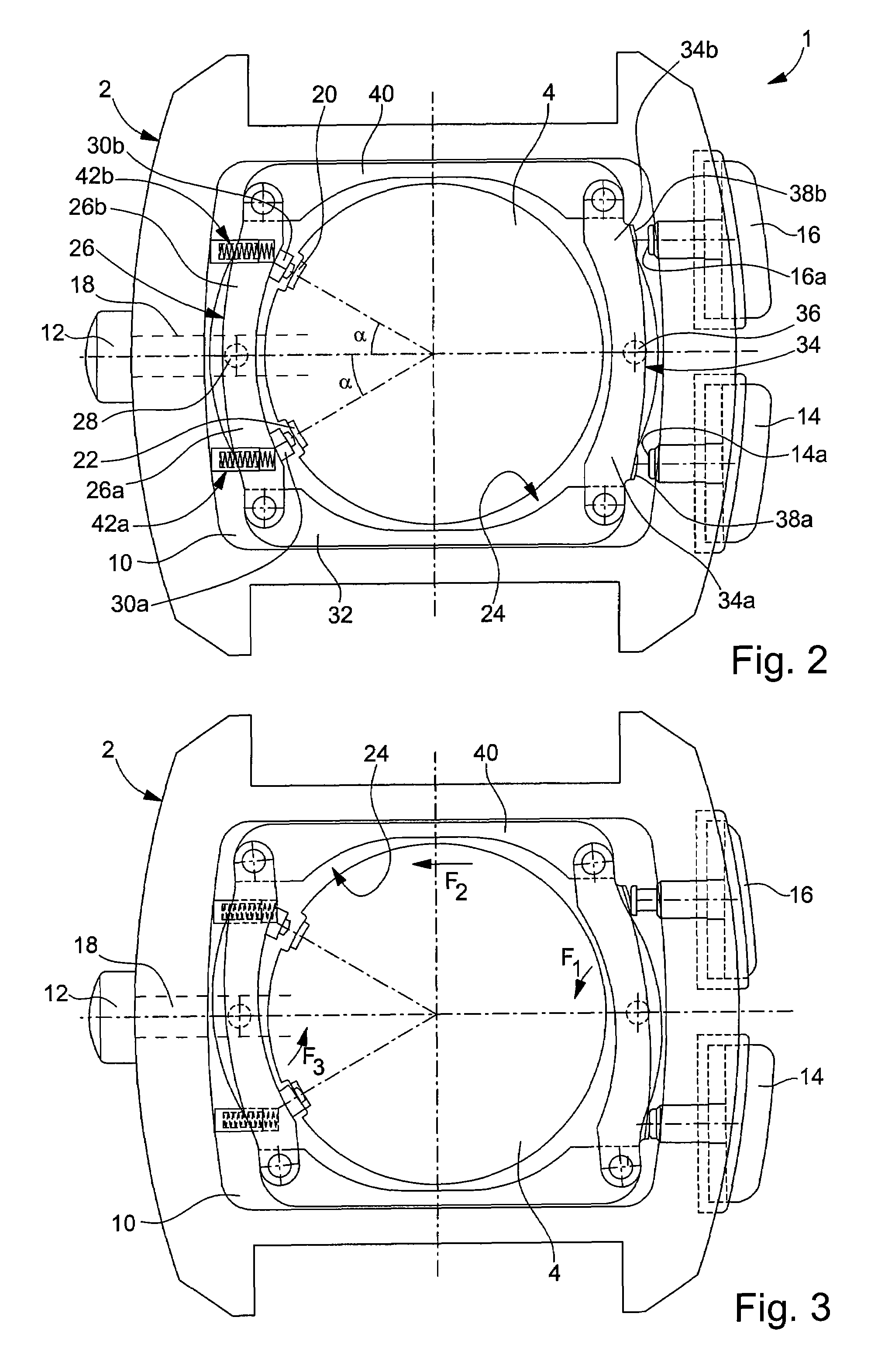
The invention is about a watch with a middle part and a movement inside. The movement has two control members on either side of the time-setting stem, which are activated by two push-buttons on the case. The watch also has an actuation device with two push-buttons that activate the control members. The watch is characterized by an angular shift between the push-buttons and the time-setting stem greater than 90 degrees. The actuation device includes a transmission mechanism that is independent of the movement and connects the push-buttons to the control members. This structure allows for watches to be made where the crown and push-buttons are on opposite sides of the case without needing a dedicated movement. The transmission mechanism is carried by the casing ring inserted between the case and movement.

Problems solved by technology

In order to obtain this configuration of the crown and push-buttons in a chronograph watch, dedicated movements must thus be used, whose cost is prohibitive if one wishes to propose such watches to consumers at an attractive price.

Method used


Image

  • Watch provided with push-buttons comprising a mechanism for actuating delocalised control elements of a clockwork
  • Watch provided with push-buttons comprising a mechanism for actuating delocalised control elements of a clockwork
  • Watch provided with push-buttons comprising a mechanism for actuating delocalised control elements of a clockwork

Examples


Embodiment Construction

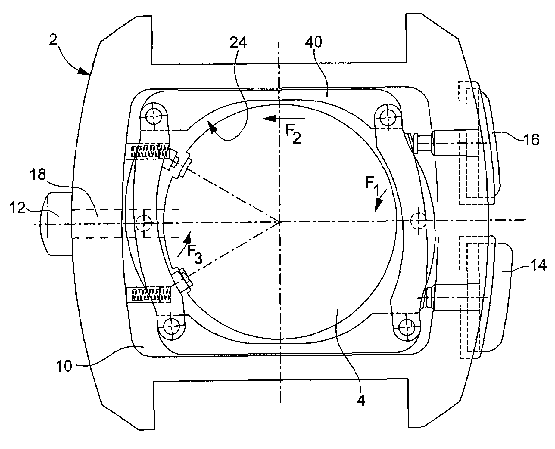
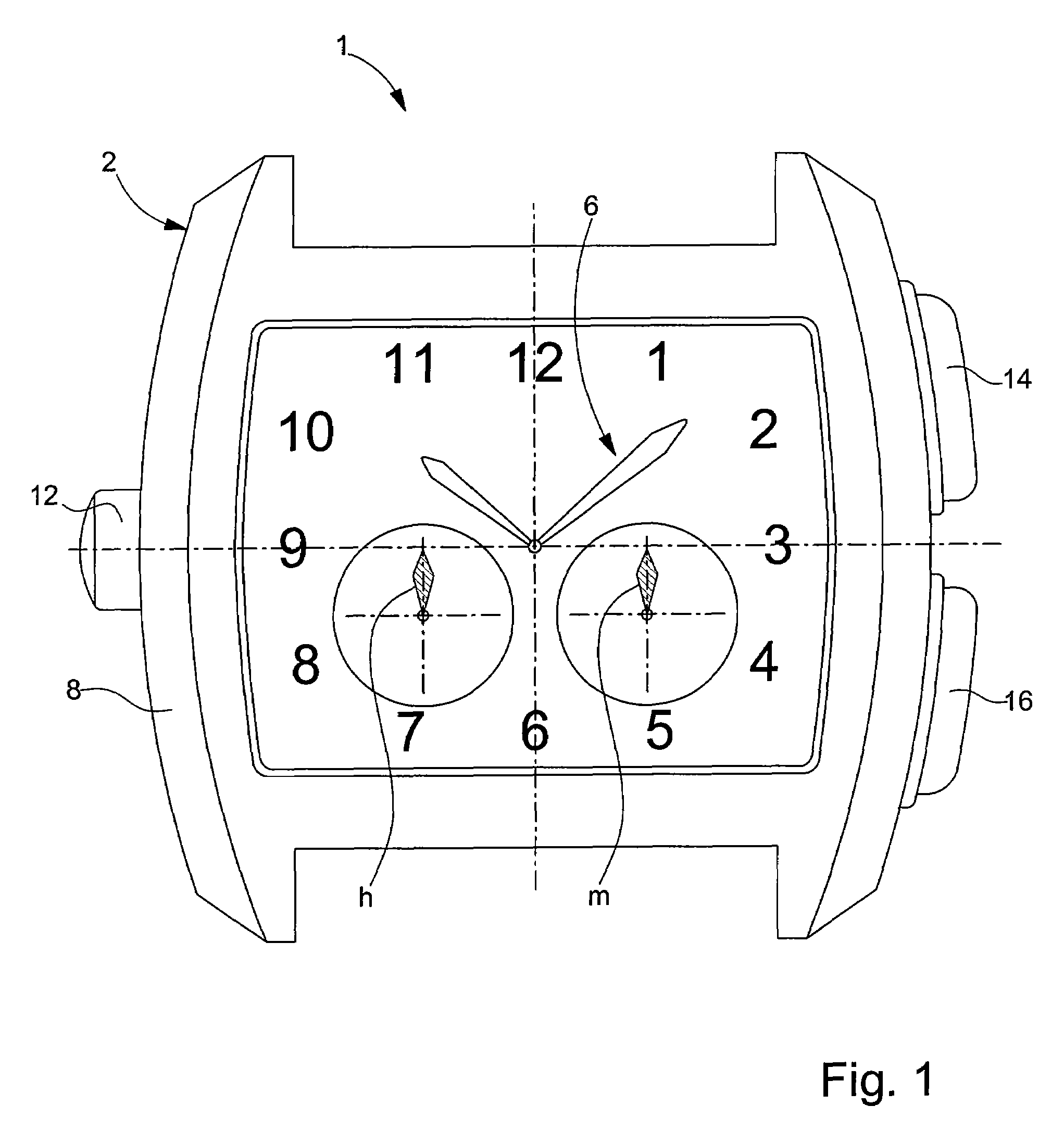
[0017]FIGS. 1 to 3 show an embodiment of a watch according to the invention, generally designated by the reference numeral 1. In the example shown, watch 1 includes a case 2 enclosing a watch movement 4 (FIGS. 2 and 3) fitted with a chronograph mechanism, time display means 6, including in this case hands and a dial graduated over 12 hours and chronograph indicators for displaying a period of time, in this case a first small hand m for counting the minutes and a second small hand h for counting the hours. Movement 4 may be a manually or automatically wound mechanical movement or an electronic movement, for example quartz, powered by a battery. Case 2 includes, in a conventional manner, a middle part 8, a crystal and a back cover (not shown) and a casing ring 10 inserted between the middle part and the movement and via which movement 4 is mounted in the case.

[0018]Watch 1 is fitted with a crown 12 arranged at 9 o'clock and two push-buttons 14 and 16, respectively at 2 o'clock and 4 o...


PUM


Abstract

The invention concerns a watch including a case having a middle part and housing a watch movement having a time-setting stem in a first peripheral region, said movement further including a first and a second control member which are arranged on either side of the time-setting stem and which each have an angular shift of less than 90° with the time-setting stem in relation to the centre of the movement, the watch further including an actuation device including a first and a second push-button arranged on the case in proximity to the movement, for respectively actuating said first and second control members,said watch being characterized in that, between each of said first and second push-buttons and said time-setting stem, there is an angular shift greater than 90° in relation to the centre of the movement, in thatsaid first and second push-buttons are arranged in a second peripheral region of said watch movement, in thatsaid actuation device further includes a transmission mechanism extending between said first push-button and said first control member, on the one hand, and between said second push-button and said second control member on the other hand, and in thatsaid transmission mechanism is independent of said watch movement.

Description

[0001]This is a National Phase Application in the United States of International Patent Application No. PCT / EP2004 / 014518 filed Dec. 21, 2004, which claims priority on European Patent Application No. 04000326.1, filed Jan. 9, 2004 The entire disclosures of the above patent applications are hereby incorporated by reference.FIELD OF THE INVENTION[0002]The present invention concerns a watch fitted with push-buttons including a mechanism for actuating control members of a timepiece movement which are delocalised in relation to the push-buttons. More specifically, the invention concerns a watch of this type including a chronograph type timepiece movement, wherein the time-setting stem and the chronograph function control members are arranged on the same side of the movement, typically at 9 o'clock for the time-setting stem, and at 8 o'clock and 10 o'clock for the control members and wherein the two chronograph function control push-buttons are respectively arranged at 2 o'clock and 4 o'c...

Claims


Application Information

Patent Timeline
Patent Type & Authority Patents(United States)
IPC IPC(8): G04B19/06G04B3/00G04B3/04G04C3/00G04F7/08G04G21/00
CPCG04B3/008G04B3/048G04C3/005G04F7/08G04F7/0861
Inventor SAUNIER, ANDRE
Owner TISSOT SA
Learn More