Battery-powered light source device for endoscope

a light source device and endoscope technology, applied in the field of light source lamps, can solve the problems of troublesome connection of the auxiliary power supply unit, difficult to supply the proper voltage to the light source lamp, and more difficult to attach to and detach from the endoscope control, so as to achieve the effect of making brighter and easy to us

Active Publication Date: 2010-08-10
OLYMPUS CORP
View PDF4 Cites 82 Cited by
  • Summary
  • Abstract
  • Description
  • Claims
  • Application Information

AI Technical Summary

Benefits of technology

[0018]It is an object of the present invention to provide a compact battery-powered light source device for an endoscope, which can be removably attached to an endoscope, and with which the light source lamp can be made brighter easily, without having to use an auxiliary power supply unit.
[0019]It is a further object of the present invention to provide a battery-powered light source device with which the optimal voltage can be supplied to the light source lamp, and the energy of the battery can be used efficiently.
[0020]It is a further object of the present invention to provide a battery-powered light source device with which the voltage is monitored and the step-up circuit is shut down when the capacity of the battery is diminished, so that the power supply circuit can be protected.
[0021]It is a further object of the present invention to provide a compact battery-powered light source device with an effectively disposed power supply circuit substrate.
[0022]It is a further object of the present invention to provide a battery-powered light source device for an endoscope, with which battery life is monitored and just the power applied to the lamp is controlled, so that the user can be apprised of a low battery, the load can be forcibly limited, and the overdischarging of the battery can be prevented.

Problems solved by technology

Here, because the above-mentioned battery-powered light source device has to be connected to an external power supply, the connection of the auxiliary power supply unit is troublesome.
Also, because the voltage is boosted in stages when the auxiliary power supply unit is used with the above-mentioned battery-powered light source device for an endoscope, it is difficult to supply the proper voltage to the light source lamp.
However, a battery-powered light source device in which the illuminating lamp is made to shine more brightly by increasing the number of batteries as above becomes larger and heavier, which makes it more difficult to attach to and detach from the endoscope control.
Another problem with a battery-powered light source device is that when the battery voltages drops as the battery is used, the input current has to be increased in order to keep the voltage of the output consistent.
Consequently, the power supply circuit is subjected to stress in a conventional battery-powered light source device.
However, with a protection circuit in which the current is monitored and an FET is used to switch off the device, there is greater loss in the resistors used for monitoring the current, the high ON resistors of the FET, and so on, which is a problem in that the energy of the battery cannot be used as efficiently.
In view of this, in Japanese Patent Application 2000-22405, which has already been submitted by the present applicant, the user was apprised of a low battery state by the provision of a second output state in which the output of the DC / DC [converter] was not as bright as usual, but the problem was that if the user kept on using the device, the terminal voltage would be exceeded and overdischarging would result.
Also disclosed was a means for flashing a lamp using an FET and thereby notifying the user, but the problem was that if the power applied to the lamp fluctuated, then the power of the control means would fluctuate at the same time, and another problem was that an extremely large surge current flowed when the lamp was turned on and off and when the power was turned on.
Accordingly, a DC / DC [converter] was generally provided both for the load and for the control means, and it was difficult to share a power supply between the load and the control means with a single DC / DC converter, and thereby protect the batter and control the load.

Method used


Image

  • Battery-powered light source device for endoscope
  • Battery-powered light source device for endoscope
  • Battery-powered light source device for endoscope

Examples


second embodiment

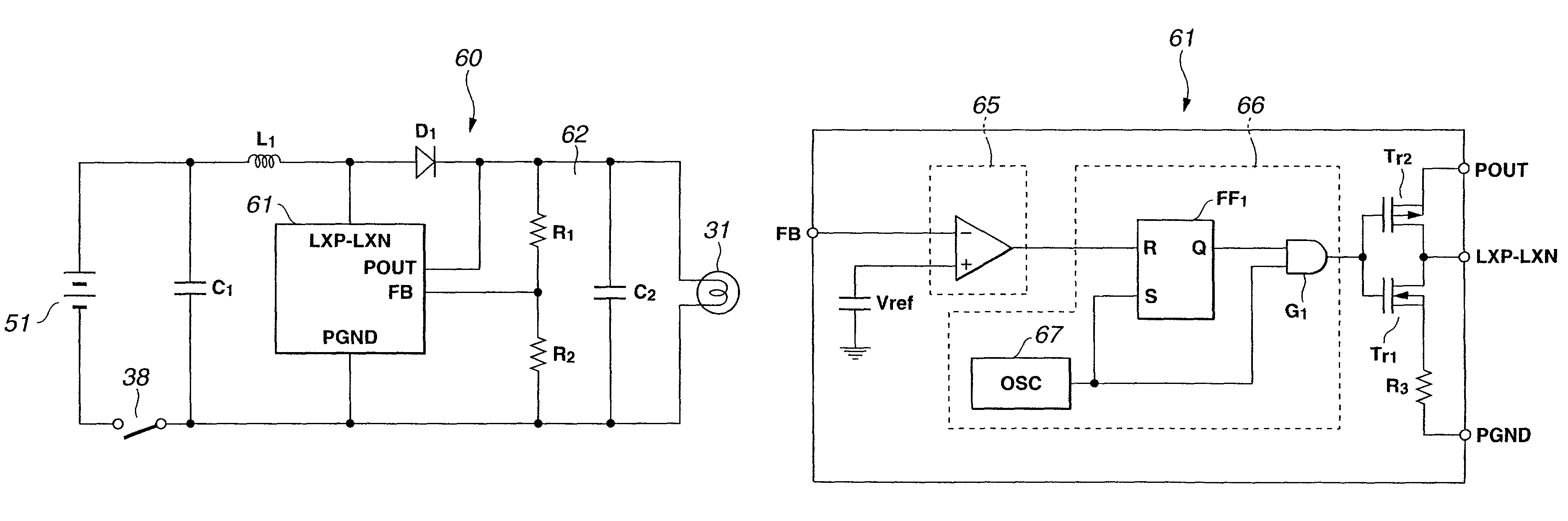
[0126]FIG. 6 is a circuit block diagram illustrating the power supply circuit of the battery-powered light source pertaining to the present invention.

[0127]In the first embodiment discussed above, two cells or other batteries 51 were connected in series, and the supply voltage from these two batteries was boosted, but in this second embodiment, at least one battery can be used with a change-over switch. The rest of the structure is substantially the same as in FIG. 3, and will therefore not be described again, and those components that are the same are labeled the same.

[0128]Specifically, a power supply circuit 70 in this second embodiment is equipped with a battery component 71 having at least two batteries 71a and 71b. The power supply circuit 70 comprises a change-over switch 72 for these batteries 71a and 71b, and a linked switch 73 for switching the potential resistors R4, R1, and R5 of the feedback component 62 linked with this change-over switch 72.

[0129]The change-over switc...

third embodiment

[0138]FIG. 7 is a circuit block diagram illustrating the power supply circuit of the battery-powered light source pertaining to the present invention.

[0139]In the first embodiment, the structure was such that current from the batteries 51 began to flow through the power supply circuit 60 all at once as soon as the on / off switch 38 was turned on, but in this third embodiment, there is provided a limiting means for limiting the initial current supplied from the batteries 51, and this prevents the lamp service life from being shortened by surge current. The rest of the structure is substantially the same as in FIG. 3, and will therefore not be described again, and those components that are the same are labeled the same.

[0140]Specifically, a power supply circuit 80 in this third embodiment is provided with a thermistor 81 whose resistance is initially high and then subsequently decreases, and which functions as a current limiting circuit for limiting the surge current that flows as curr...

fourth embodiment

[0143]FIG. 8 is a circuit block diagram illustrating the power supply circuit of the battery-powered light source pertaining to the present invention.

[0144]In the first to third embodiments above, the power supply circuit made use of a DC / DC converter 61 as the step-up circuit for boosting the supply voltage of the batteries, but in this fourth embodiment, the power supply circuit makes use of a DC / DC converter as a step-down circuit for lowering the supply voltage of the batteries. The rest of the structure is substantially the same as in FIG. 3, and will therefore not be described again, and those components that are the same are labeled the same.

[0145]Specifically, a power supply circuit 90 in this fourth embodiment comprises a battery 91, which consists, for example, of two lithium ion cells with a supply voltage of 3.5 V, connected in series for a supply voltage of 7.0 V, a step-down DC / DC converter 92 that lowers the supply voltage of this battery 91, a coil L1 that stores the...


PUM


Abstract

A battery-powered light source device 5 has an DC / DC converter 61 that boosts the supply voltage of a battery 51 and supplies electrical power to a lamp 31, and, inside this DC / DC converter 61, are provided a comparator 65 that compares a specific reference voltage to the output voltage of a DC / DC converter 61, and a control component 66 that keeps the output voltage from the DC / DC converter 61 at a specific lamp voltage on the basis of the comparison result of this comparator 65, whereby the supply voltage of the battery 51 is boosted and the optimal lamp voltage is obtained. Consequently, the battery-powered light source device 5 allows the brightness of the lamp to be adjusted and a high step-up efficiency to be obtained, and the battery can therefore be used more efficiently, and a more convenient use of the endoscope is possible.

Description

[0001]This application claims benefit of Japanese Applications No. Hei 11-343690 filed in Japan on Dec. 2, 1999, No. Hei 11-343692 filed in Japan on Dec. 2, 1999, No. 2000-017400 filed in Japan on Jan. 26, 2000, No. 2000-022405 filed in Japan on Jan. 31, 2000 and No. 2000-347118 filed in Japan on Nov. 14, 2.000, the contents of which are incorporated by this reference.BACKGROUND OF THE INVENTION[0002]1. Field of the Invention[0003]The present invention relates to a light source lamp that supplies illuminating light to an endoscope, and a battery-powered light source device for an endoscope equipped with a battery, which supplies power to this light source lamp.[0004]2. Description of the Related Art[0005]Endoscopes have come to be used in a wide range of fields today, both in medicine and industry. What these endoscopes are used to examine are the inside of the body or the inside of factory machinery or the like, and therefore some means is necessary for illuminating the site to be ...

Claims


Application Information

Patent Timeline
Patent Type & Authority Patents(United States)
IPC IPC(8): G05F1/00A62B1/04
CPCA61B1/00034A61B1/0669
Inventor HOSODA, SEIICHIYAMAKI, MASAHIDEWATANABE, KATSUSHITAKAHASHI, HIROSHIGOTANDA, MASAKAZUOSAKI, ITARUNAKAMURA, TAKEAKI
Owner OLYMPUS CORP
Why Eureka
Try Eureka