RFID tag sensors and methods

a technology of rfid tags and sensors, applied in the field of rfid tags, can solve the problems of significant difficulties for vendors in implementing rfid systems, mismatched greater impedances, and low success rate of rfid read rates

Active Publication Date: 2011-01-20
WALMART APOLLO LLC
View PDF36 Cites 50 Cited by
  • Summary
  • Abstract
  • Description
  • Claims
  • Application Information

AI Technical Summary

Problems solved by technology

However, vendors face significant difficulties implementing RFID systems.
For example, the successful read rates currently run only 80%, due to radio wave attenuation caused by the products and packaging.
The more the antenna is detuned, the greater the impedance is mismatched.
The tag's performance degrades as the impedance mismatch increases until the tag stops working.
Inlay manufacturers have had only moderate success at designing “universal tags” that will reliably function for all uses.
As a further challenge, vendors wil...

Method used


Image

  • RFID tag sensors and methods
  • RFID tag sensors and methods
  • RFID tag sensors and methods

Examples


Embodiment Construction

[0054]The following description is not to be taken in a limiting sense, but is made merely for the purpose of describing the general principles of exemplary embodiments. The scope of the invention should be determined with reference to the claims.

[0055]Reference throughout this specification to “one embodiment,”“an embodiment,” or similar language means that a particular feature, structure, or characteristic described in connection with the embodiment is included in at least one embodiment of the present invention. Thus, appearances of the phrases “in one embodiment,”“in an embodiment,” and similar language throughout this specification may, but do not necessarily, all refer to the same embodiment.

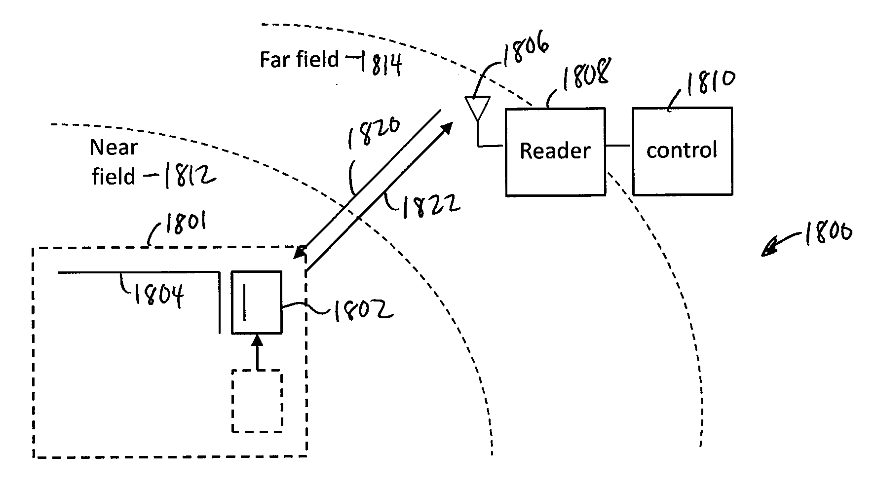
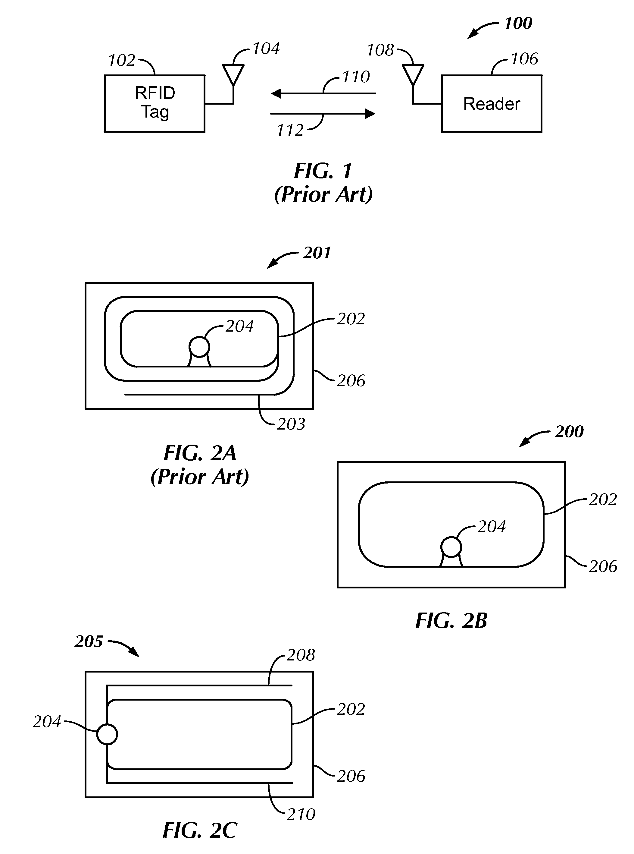
[0056]According to several embodiments, the design of the near field RFID tag component and the far field antenna of a typical RFID tag is decoupled. For example, in one embodiment, the design of the near field RFID tag component is independent of the design of the far field antenna that w...


PUM


Abstract

Radio frequency identification (RFID) devices for use in RFID-based sensors and related methods are described herein. In one implementation, an RFID sensor system includes an RFID device having a near field only RFID tag and a conductive element which functions as a far field antenna. A coupling structure selectively locates the near field only RFID tag and the conductive element in at least a first position and a second position relative to each other; wherein in the first position, the RFID device only operates in a near field, and in the second position, the RFID device operates in both the near field and a far field. The system may also include an RFID reader and controller located within the far field to read the RFID device only when the coupling structure locates the components in the second position.

Description

[0001]This application is a continuation-in-part of U.S. application Ser. No. 12 / 721,527, filed Mar. 10, 2010, entitled UNIVERSAL RFID TAGS AND MANUFACTURING METHODS, which claims the benefit of U.S. Provisional Application No. 61 / 159,042, filed Mar. 10, 2009, both of which are incorporated in their entirety herein by reference.BACKGROUND OF THE INVENTION[0002]1. Field of the Invention[0003]The present invention relates generally to radio frequency identification (RFID) tags, and more specifically to RFID tags suitable for use in near and far range applications.[0004]2. Discussion of the Related Art[0005]A radio frequency identification (RFID) tag is an object that can be applied to or incorporated into a product, animal, or person for the purpose of identification and tracking using radio waves. Some tags can be read from several meters away and beyond the line of sight of the reader. Most RFID tags contain at least two parts. One is an integrated circuit for storing and processing...

Claims


Application Information

Patent Timeline
IPC IPC(8): G06K7/01
CPCG06K7/10178G06K7/10297G06K19/07749
Inventor WILKINSON, BRUCE W.
Owner WALMART APOLLO LLC
Why Eureka
Try Eureka