Display with Slide Structure

a slide structure and display technology, applied in the field of display, can solve the problems of inability to achieve thin character, torque-type pedestal b>8/b>, inconvenient for people to push the display by means of only one hand, etc., and achieve the effect of thin character

Active Publication Date: 2011-01-27
TOP VICTORY INVESTMENTS
View PDF4 Cites 2 Cited by
  • Summary
  • Abstract
  • Description
  • Claims
  • Application Information

AI Technical Summary

Benefits of technology

The primary object of present invention is to save the space occupation of the connecting stand, so that the display may achieve thin character.
Whereby, the display with slide structure of present invention could reduce space occupation and manufacturing cost of the display, simplify the mechanical configuration and maximize the tilted angle of the display by only one hand, so as to achieve thin character. In addition, the components of the display are relatively few and the configuration is also simple, therefore the failure rate, manufacture and maintenance cost may be absolutely reduced as well. Furthermore, pluralities of springs could sustain larger and heavier display. Therefore, the present invention may have several advantages and improve convenience, and thus has extremely market potential.

Problems solved by technology

It's bulky and space-wasted, so that the display might not achieve thin character.
Besides, the torque-type pedestal 8 is also inconvenient for people to push the display tilted by means of only one hand.
However, force-type pedestal 9 is also space-wasted, so that it cannot be achieved thin character.
Moreover, the force-type pedestal 9 is expensive, complicated, and has high failure rate and too many components to be conveniently maintained.
Thus, how to reduce space occupation and manufacturing cost, simplify the mechanical configuration and maximize the tilted angle of the display by only one hand, is a critical issue needed to be settled.

Method used


Image

  • Display with Slide Structure
  • Display with Slide Structure
  • Display with Slide Structure

Examples


Embodiment Construction

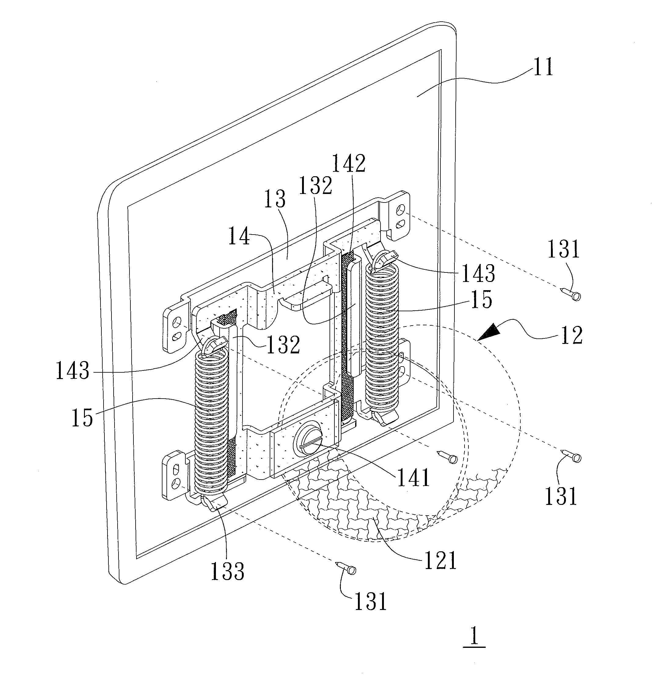
Please refer to FIG. 3, FIG. 3 is diagram depicting the display with slide structure while the springs are not yet stretched. As shown in FIG. 3, a display 1 includes a rear casing 11, a stand 12, a fixing unit 13, a movable unit 14 and two springs 15. The fixing unit 13 is disposed at the rear casing 11 by means of fastening the corner of the fixing unit 13 to the rear casing 11 by pluralities of screws 131, and as a result the fixing unit 13 is firmly fixed. The fixing unit 13 contains two hook-shaped first holding parts 133 at bottom half and two rails 132. The movable unit 14 is disposed near the fixing unit 13 and is connected to the stand 12 by means of the fastened screw 141. The stand 12 contains a curved-shaped arc structure 121 disposed at bottom half of the stand 12. Wherein, the shape of the arc structure 121 could be circular arc, elliptical arc or the arc with variant curvature. The stand 12 and the movable unit 14 could be repeatedly moved up and down by means of two ...


PUM


Abstract

The present invention is related to a display with slide structure. The display comprises a rear casing, a stand, a fixing unit, a movable unit and at least one spring. The stand has an arc structure disposed beneath. The fixing unit is firmly disposed at the rear casing and contains at least one first holding part and at least one rail. The movable unit connects with the stand and contains at least one second holding part; wherein the movable unit is repeatedly movable by means of the rail. The spring is respectively connected to the first holding part and the second holding part with two ends. Whereby, the stand could be repeatedly movable against the rear casing by means of the movable unit and touch a flat surface by distinct sites of the arc structure, so that the display might maximize its inclined angle.

Description

FIELD OF THE INVENTIONThe present invention relates to a display, particularly to a display with slide structure.DESCRIPTION OF THE PRIOR ARTIn recent year, due to the cost down of the flat panel display, the display has gradually come into vogue in home TV and computer display. Besides, because of its thinness and light characters comparative to cathode-ray-tube television, the flat panel display will be more and more favorable and easily seen in public such as station, hospital, convenient store or theater. Those flat panel displays not only can be utilized to deliver message, but also can achieve some advertising purpose. Thus, the usage and application of flat panel display will be wider and wider.Please refer to FIG. 1, FIG. 1 is diagram of torque-type pedestal of conventional display. As shown in FIG. 1, a torque-type pedestal 8 of conventional display (not shown) includes a fixing unit 83 and a rotative unit 86. The linkage area of the fixing unit 83 and the rotative unit 86 ...

Claims


Application Information

Patent Timeline
IPC IPC(8): H05K7/00
CPCF16M11/046F16M2200/047F16M13/00F16M11/10G06F1/1601G06F2200/1612
Inventor LIU, HUAI SHENG
Owner TOP VICTORY INVESTMENTS
Why Eureka
Try Eureka