Method and apparatus for a switching mode power supply

a power supply and switching mode technology, applied in the direction of ac-dc conversion, dc-ac conversion without reversal, ac-dc conversion, etc., can solve the problems of large noise, many limitations of conventional smps, electromagnetic interference at the switching frequency or harmonic of power transistors, etc., to reduce the current drain of controllers, reduce the instability of the supply voltage of the controller, and reduce the effect of instability

Active Publication Date: 2011-01-27
BCD SHANGHAI MICRO ELECTRONICS CO LTD
View PDF10 Cites 80 Cited by
  • Summary
  • Abstract
  • Description
  • Claims
  • Application Information

AI Technical Summary

Benefits of technology

[0010]In an embodiment, a controller according to the invention includes a detection circuit for detecting a change in the output load condition from a heavy load to a light load and a control circuit that disables certain functional blocks of the controller in response to the detected load change in order to reduce the current drain of the controller. It has been observed that by reducing the current drain of the controller during the light load condition, instability at the supply voltage of the controller can be minimized. In another embodiment, the instability can be reduced by supplying more power to the output.
[0011]In another embodiment of the present invention, a controller device includes a comparator having an input for receiving a feedback signal and configured to compare the feedback signal with a reference voltage. The result of the comparison is then delayed in a delay circuit, and the delayed control signal is then used to turn on and off a high voltage source in order to increase the charging rate of the power supply of the controller device and to compensate for the current drain when the power switch remains inactive.

Problems solved by technology

On the other hand, they also have the disadvantages of greater noise, especially Electromagnetic Interference at the power transistor's switching frequency or its harmonics.
Even though widely used, conventional SMPS has many limitations.
For example, during transition of different output load conditions, especially during relatively large load changes, the SMPS may exhibit unstable output voltages, as described in more detail below.

Method used


Image

  • Method and apparatus for a switching mode power supply
  • Method and apparatus for a switching mode power supply
  • Method and apparatus for a switching mode power supply

Examples


first embodiment

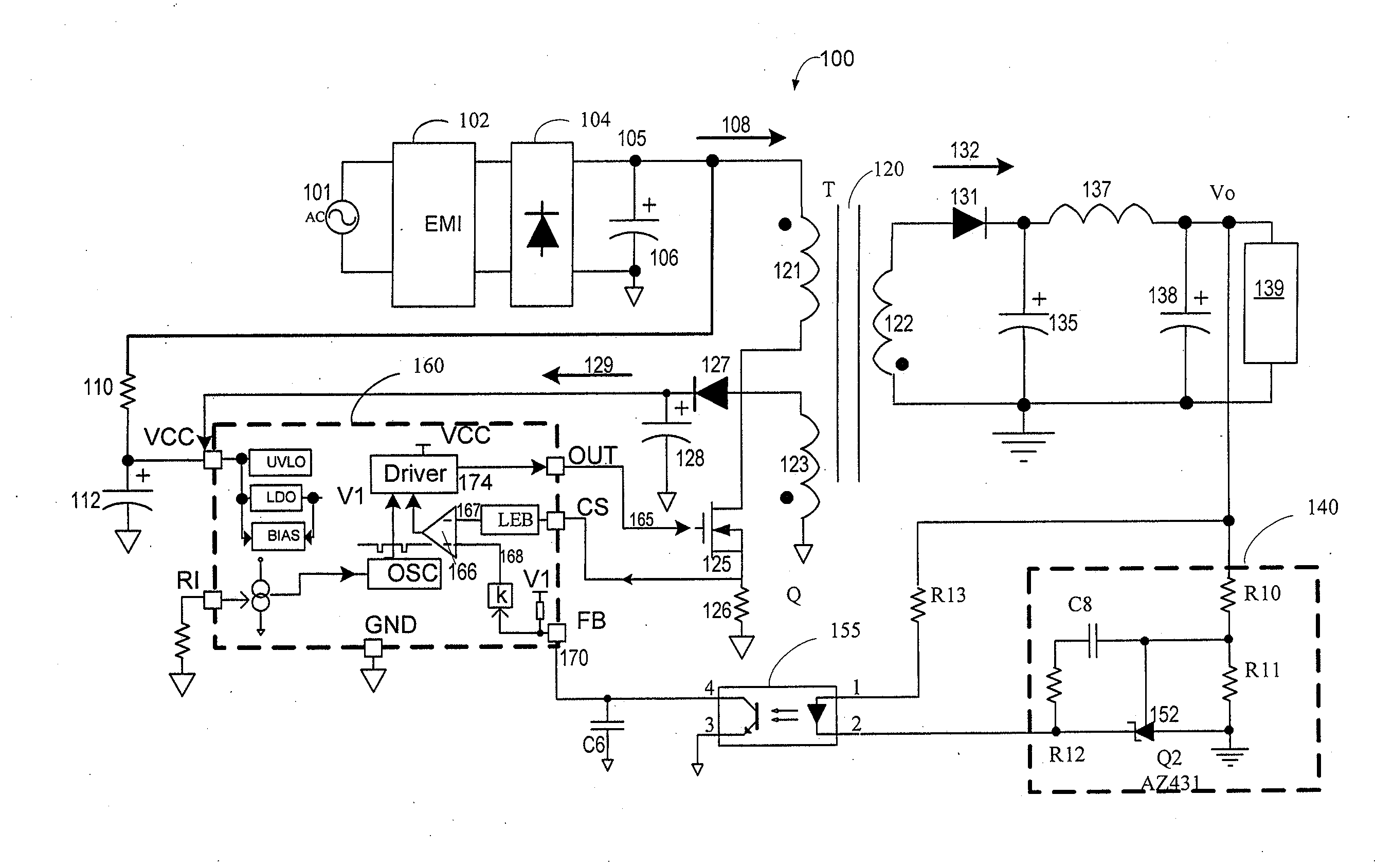
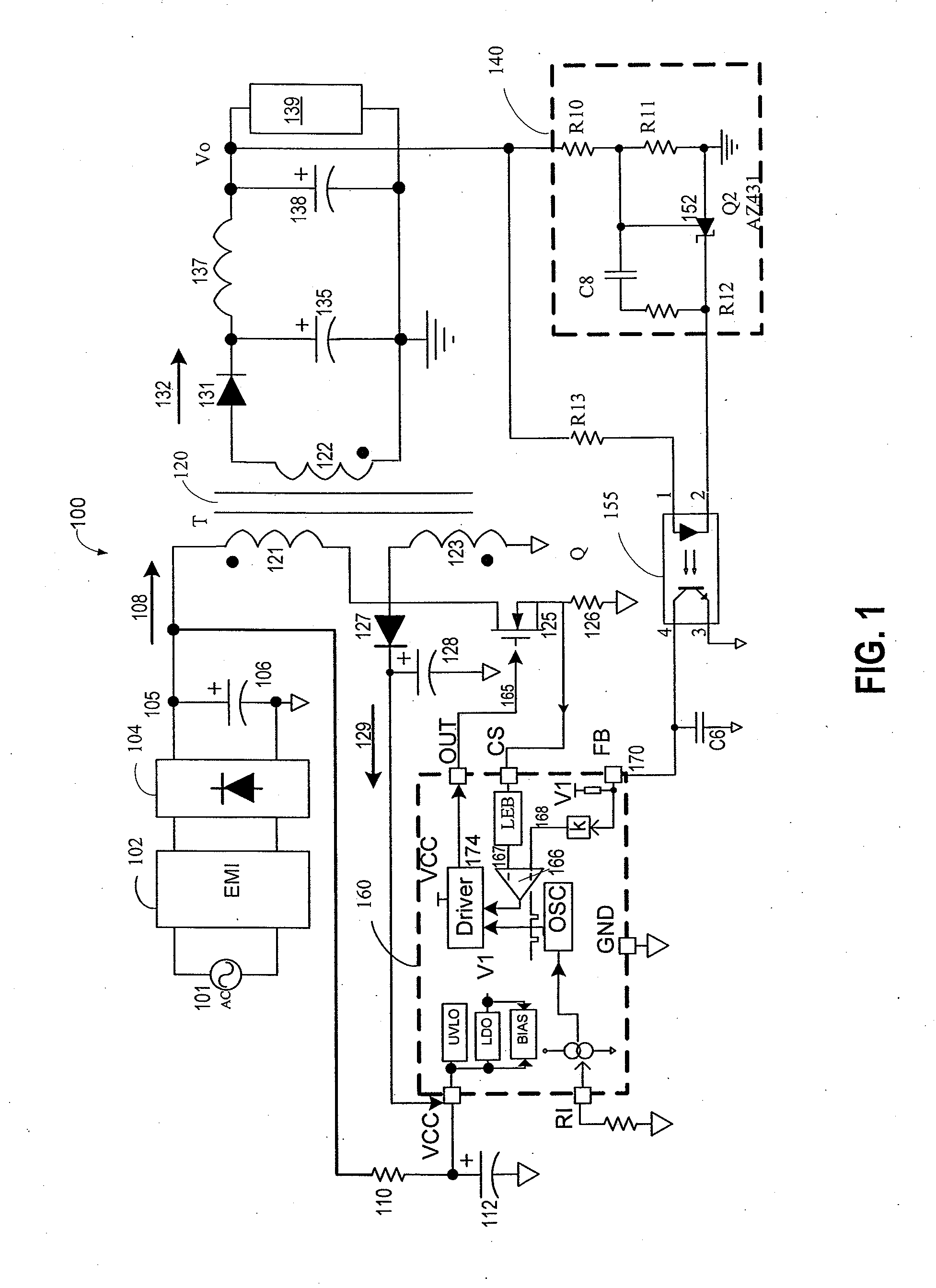
[0040]FIG. 3 is a simplified functional block diagram of a switching mode power supply 300 including selected circuit blocks of a controller 360 in accordance with the present invention. Some of the circuit blocks are similar to those shown in FIG. 1 and are omitted here to simplify the drawing. As shown, switching mode power supply 300 includes a transformer having a primary winding 321, a secondary winding 322, and an auxiliary winding 323. Switching mode power supply 300 further includes a controller 360. In one embodiment, controller 360 is implemented using a very high voltage integrated circuit (VHVIC) technology to allow a direct coupling to the high voltage source such as the primary winding 321. Controller 360 can derive its internal power supplies from the high voltage input HV. Controller may also receive a power supply from a secondary winding through rectifier 327 and a capacitor 328. At power-on or start up phase, capacitor 328 is charged through the high voltage sourc...

second embodiment

[0041]FIG. 4 is a simplified block diagram illustrating a switching mode power supply 400 including selected functional blocks of a controller 460 in accordance with the present invention. It is understood that controller 460 may include circuit blocks described above in connections with FIGS. 1 and 3. Switching mode power supply 400 includes a transformer having a primary winding 421, a secondary winding 422, and an auxiliary winding 423. Comparator 410 is coupled with a feedback signal ZCD that is derived of a resistive divider R3 / R4 coupled to auxiliary winding 423. Feedback signal ZCD reflects both the change of the regulated output voltage Vo and input voltage (node 105). ZCD can further be scaled by multiplying with an average value 453 of the current sensing voltage CS that reflects the current flowing across power switch 425. The scaled product 454 indicating the output power is then compared with a reference voltage V2 at comparator 410, whose output is coupled to logic cir...

third embodiment

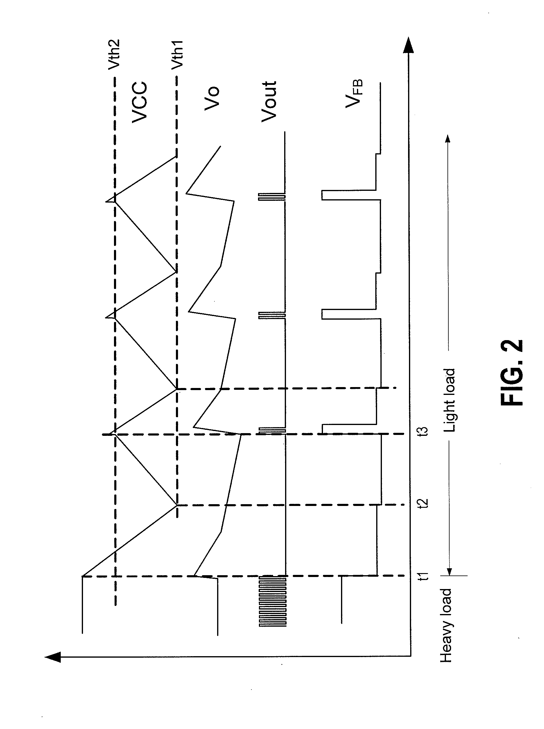
[0042]FIG. 5 is simplified block diagram of a switching mode power supply 500 including selected functional blocks of a controller 560 for in accordance with the present invention. It is understood that controller 560 may include circuit blocks described above in connections with FIGS. 1, 3, and 4. As shown in FIG. 5, switching mode power supply 500 includes a transformer having a primary winding 521, a secondary winding 522, and an auxiliary winding 523. Comparator 510 is coupled with a feedback signal FB that is then compared with a reference voltage V2. If the voltage of feedback signal FB is lower than reference voltage V2, comparator will produce a positive signal 512 at its output. Positive signal 512 is coupled to an AND gate 520 whose other input is coupled to a clock signal 540. Clock frequency 540 is used to enable a driver logic block 530 to turn on and off a power switch 525. By turning on and off power switch 525, the voltage supply Vcc of controller 560 will be maintai...


PUM


Abstract

A controller for a switched mode power supply (SMPS) is provided. The SMPS is equipped with a transformer having a primary side winding, a secondary winding, and an auxiliary winding. The controller includes a detection circuit for detecting a transition from a first output load condition to a second output load condition of the SMPS and a control circuit coupled to the detection circuit and being configured to output one or more control signals in response to the detected output load transition. Depending on the embodiment, the one or more control signals include a first control signal for turning on a power switch to cause a current flow in a primary winding of the SMPS and / or one or more second control signals for turning off one or more functional circuit blocks in the controller.

Description

CROSS-REFERENCES TO RELATED APPLICATIONS[0001]This application claims priority to Chinese Patent Application No. 200920163199.4 filed Jul. 22, 2009 by inventors Quanqing Wu, et. al., commonly assigned and incorporated in its entirety by reference herein for all purposes.BACKGROUND OF THE INVENTION[0002]Embodiments of the present invention are directed to power supply control circuits and power supply systems. More particularly, embodiments of the present invention provide methods and circuits for controlling a switching mode power supply (SMPS). Merely as an example, the methods and circuits have been applied in controlling an SMPS during a transition of load conditions. But embodiments of the invention have a much wider applicability.[0003]Regulated power supplies are indispensable in modern electronics. For example, the power supply in a personal computer often needs to receive power input from various outlets. Desktop and laptop computers often have regulated power supplies on th...

Claims


Application Information

Patent Timeline
Patent Type & Authority Applications(United States)
IPC IPC(8): H02M7/44
CPCH02M3/33523Y02B70/16H03K7/08H02M2001/0035H02M1/0035Y02B70/10
Inventor WU, QUANQINGREN, XUEGANGZHAO, XIANGYUAN
Owner BCD SHANGHAI MICRO ELECTRONICS CO LTD
Why Eureka
Try Eureka