Torque Reduction System for Archery Bows

Inactive Publication Date: 2011-02-03
LIGHT WILLIAM T +1
View PDF8 Cites 5 Cited by
  • Summary
  • Abstract
  • Description
  • Claims
  • Application Information

AI Technical Summary

Benefits of technology

[0015]In accordance with one embodiment of the present disclosure a torque reduction system is provided. The torque reduction system provides a means of positioning stabilization elements on or in close proximity to the transverse axis of the archery Bow. More particularly, lightweight masses and / or shock-absorbing elements can be mounted onto the torque reduction system on the axis of or in close proximity to the throat of the archery Bow handle, thereby reducing any lateral torque caused by the archer's grip on the archery Bow handle.
[0016]One effect of the location of the torque reduction system is the reduction of right and left torque resulting in better and more consistent arrow flight. It also provides the possibility of the archer shooting lighter arrows and a lighter spined arrow. The attachment of energy absorbing elements at or close to the throat of the archery bow handle allows the archer to manipulate the dynamic spine of the arrow. The flight of the arrow as it is launched from the bow is thereby positively affected.
[0017]In one embodiment, the torque reduction system comprises two elements rigidly connected. This configuration provides versatility in adapting the torque reduction system to various archery Bow configurations. The upper portion of the torque reduction system allows mounting the stabilization elements on or in the proximity of the transverse axis of the archery Bow. The offset dimension of the vertical upper portion of the torque reduction system provides maximum rigidity along the transverse axis of the stabilization elements. The horizontal offset dimension of the upper portion of the torque reduction system provides clearance for the archer's hand while gripping the archery Bow handle. The position of the mounting holes used to attach the base portion of the torque reduction system to the archery Bow further enhances its versatility.

Problems solved by technology

All archery bows are subject to torque, vibrations, and movement based on inertial effects.
There is a compromise between how much stabilization weight can be added to the archery Bow and the resultant fatigue of the archer.
This limits, in practice, the total amount of weight for any stabilization system that can be added.
All perform to varying degrees but compromises in the placement and means of attachment to the archery Bow limit their effectiveness.
These products however do not teach the addition of subsequent stabilizing elements and do not provide the means to mount any stabilizing elements in close proximity to the transverse axis of the archery Bow.
The ability of these types of designs to mount a single stabilizer in different discrete levels or on a continuum along the transverse axis of the device not only complicates the selection of an “optimum” position but fails to anticipate the need for a single or multiple stabilizing elements positioned on or in close proximity to the transverse axis of the archery Bow.
The various designs of archery bow handles complicate where the pressure point of the hand is when holding the archery Bow.
There is a compromise between how much stabilization weight can be added to the archery bow and the fatigue of the archer during shooting.
This limits in practice the amount of stabilization weight that can be added.
The additional effects of the design and alignment of the pulley systems further complicate the archery bow tuning.
Archer's shooting traditional archery bows are limited in the number and dimensions of allowed attachments.
None of the prior art anticipates the addition of stabilizing elements to the traditional bow in the proximity to its transverse axis.

Method used


Image

  • Torque Reduction System for Archery Bows
  • Torque Reduction System for Archery Bows
  • Torque Reduction System for Archery Bows

Examples


Embodiment Construction

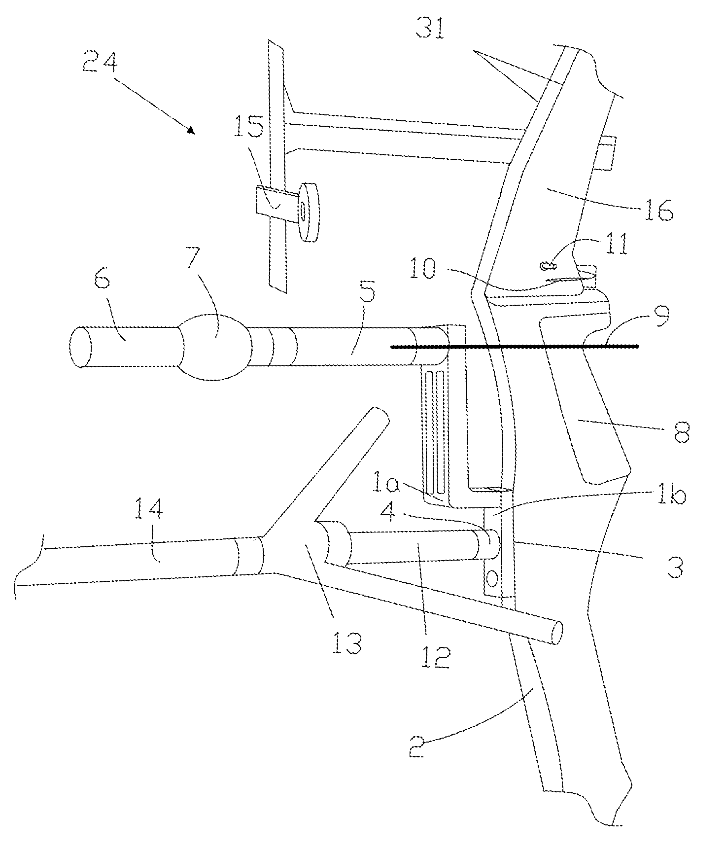
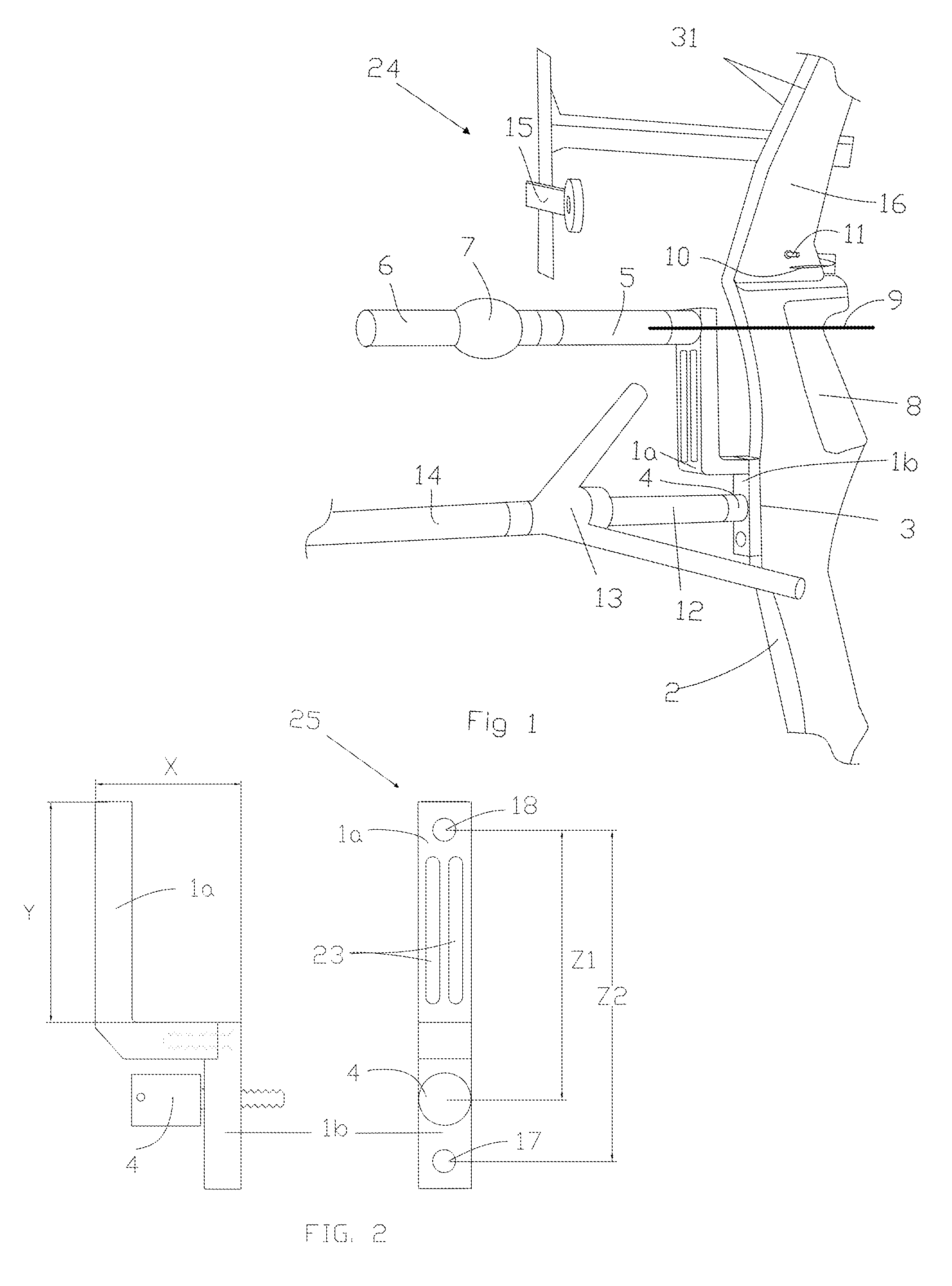
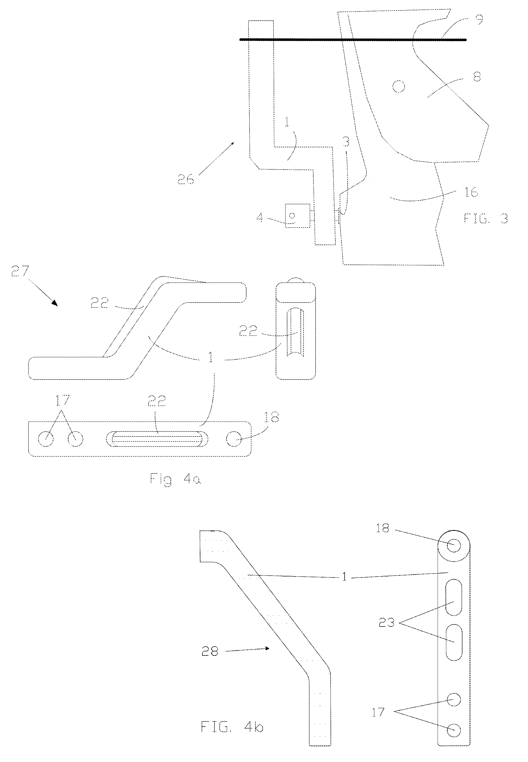
[0031]Turning now to FIG. 1, a recurve archery bow including stabilization elements and accessories attached is shown generally by reference number 24. A two-piece torque reduction system 1a and 1b is attached to the bow riser 16 with bolt 4. Other optional stabilization elements, for example, stabilizer rod 14, extension rod 12, v-bar attachment with two rods 13, are also attached to mounting surface 3 on the backside 2 of the bow 16. Other accessories attached to the bow riser 16 include a sight with extension arm 15, arrow rest 10, and plunger button 11. The energy absorbing element 7, mounting rod 5, and cap weight 6 are shown attached to the upper portion of the torque reduction device 1a. Maximum benefit occurs when the energy absorbing elements 5, 6 and 7, are mounted on the transverse axis 9 of the bow riser 16. The transverse axis 9 is defined as passing through the deepest recess on the handle also referred to as the pressure point and the throat of the handle 8. The type ...


PUM


Abstract

The torque reduction system provides a means of positioning stabilization elements on or in close proximity to the transverse axis of the archery Bow. More particularly, lightweight masses and / or shock-absorbing elements can be mounted onto the torque reduction system on the axis of or in close proximity to the throat of the archery Bow handle, thereby reducing any lateral torque caused by the archer's grip on the archery Bow handle.

Description

CROSS REFERENCE[0001]This application is claiming the benefit of provisional application number 61-230,373-1777 dated July 2010.FEDERALLY SPONSORED RESEARCH OR DEVELOPMENT[0002]Not Applicable.BACKGROUND[0003]1. Technical Field[0004]The present disclosure relates to a torque reduction system for archery bows. The torque reduction system provides a simple, positive and secure system for attaching stabilizers of various designs and configurations, shock absorbing devices, and simple weights on or close to the transverse axes of an archery bow.[0005]2. Background of Related Art[0006]All archery bows are subject to torque, vibrations, and movement based on inertial effects. These effects include, the vibration of the string after release, the effects of launching the arrow, the vibration of the limbs, the riser, the archers grip on the bow, as well as the inertial effects of attachments on the bow.[0007]Arrow spine is a critical parameter. Both the static spine and dynamic spine affect a...

Claims


Application Information

Patent Timeline
IPC IPC(8): F41B5/14F41B5/00
CPCF41B5/1426
Inventor LIGHT, WILLIAM T.PASCHKE, RICHARD H.
Owner LIGHT WILLIAM T
Why Eureka
Try Eureka