Multi-zone Screen Isolation System with selective Control

a screen isolation and multi-zone technology, applied in the direction of filtration separation, separation process, borehole/well accessories, etc., can solve the problems of reducing the flow area or drift dimension of the screen section, affecting the size of the tool, and affecting the flow distribution

Active Publication Date: 2011-02-03
BAKER HUGHES INC
View PDF16 Cites 47 Cited by
  • Summary
  • Abstract
  • Description
  • Claims
  • Application Information

AI Technical Summary

Problems solved by technology

This configuration required multiple sliding sleeve valves that had to be operated and created issues of flow distribution within a given zone.
The other lingering issue of the prior designs with the location of the sliding sleeves inside the base pipe flow bore and directly under the screen assembly that covered the base pipe was that the resulting flow area or drift dimension of the screen section was diminished which limited the size of tools that could get through a given screen as well as created flow constrictions that could limit production or require the use of artificial lift techniques that consume additional power and create other costs for procurement and installation.

Method used


Image

  • Multi-zone Screen Isolation System with selective Control
  • Multi-zone Screen Isolation System with selective Control
  • Multi-zone Screen Isolation System with selective Control

Examples


Embodiment Construction

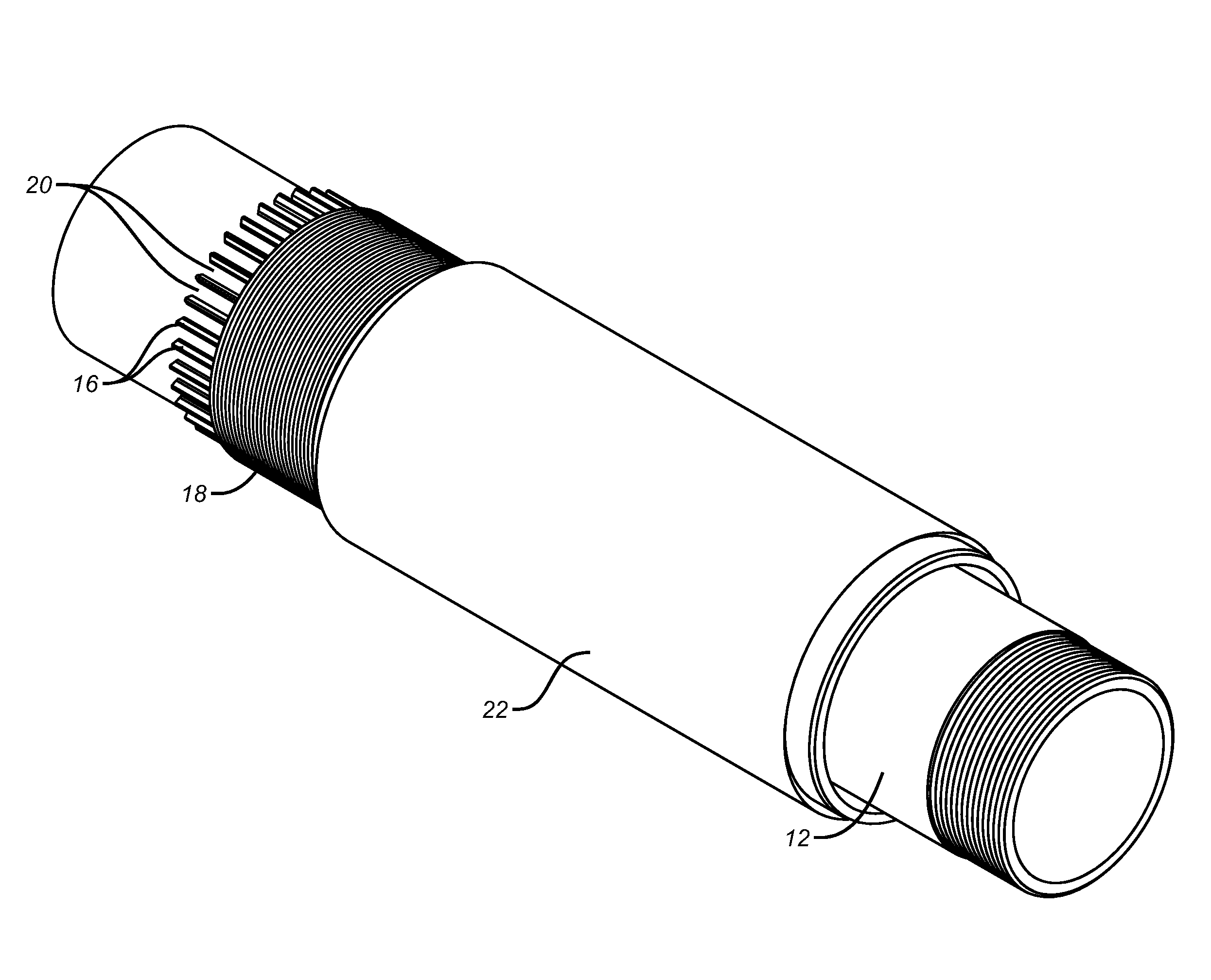
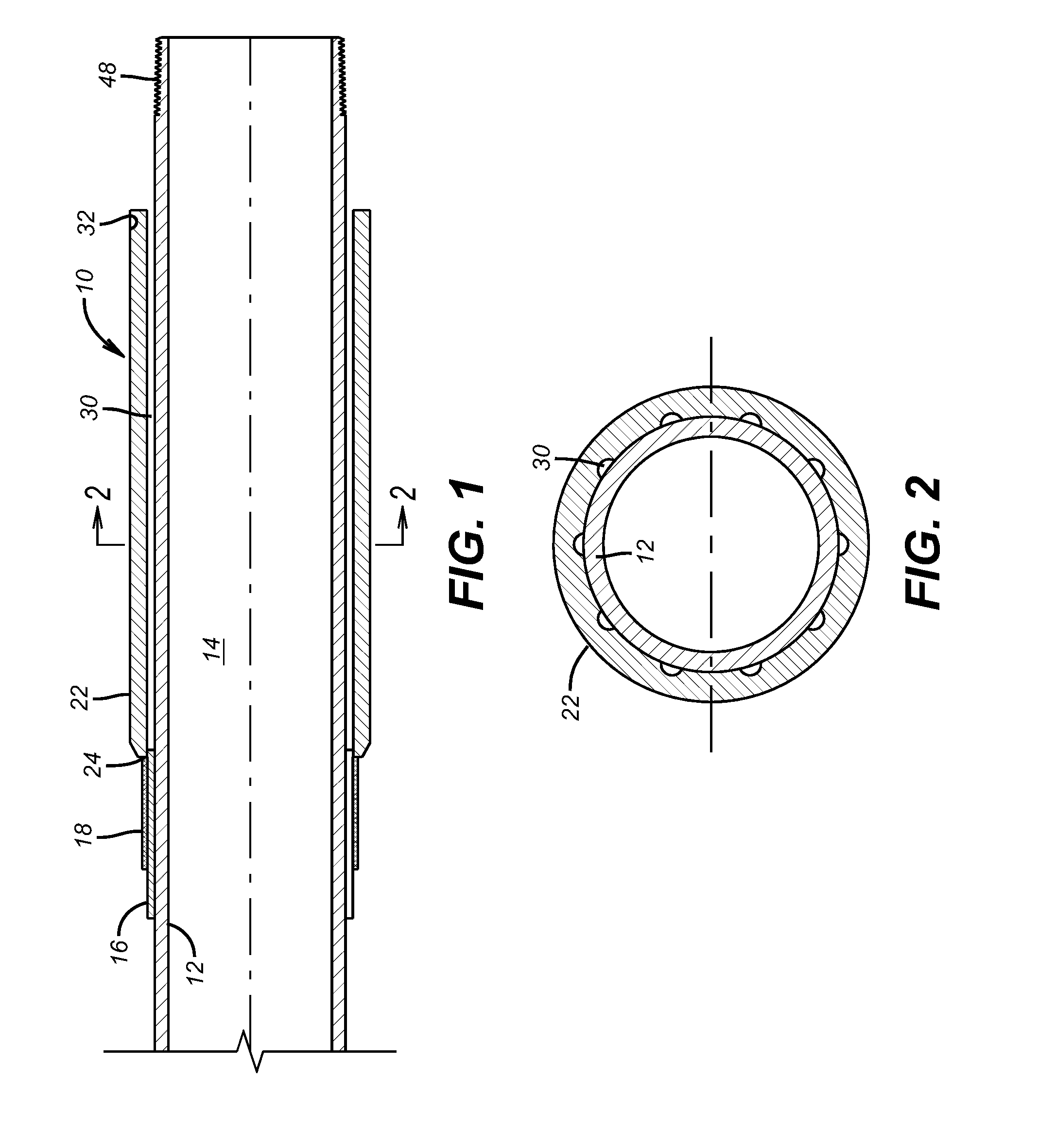
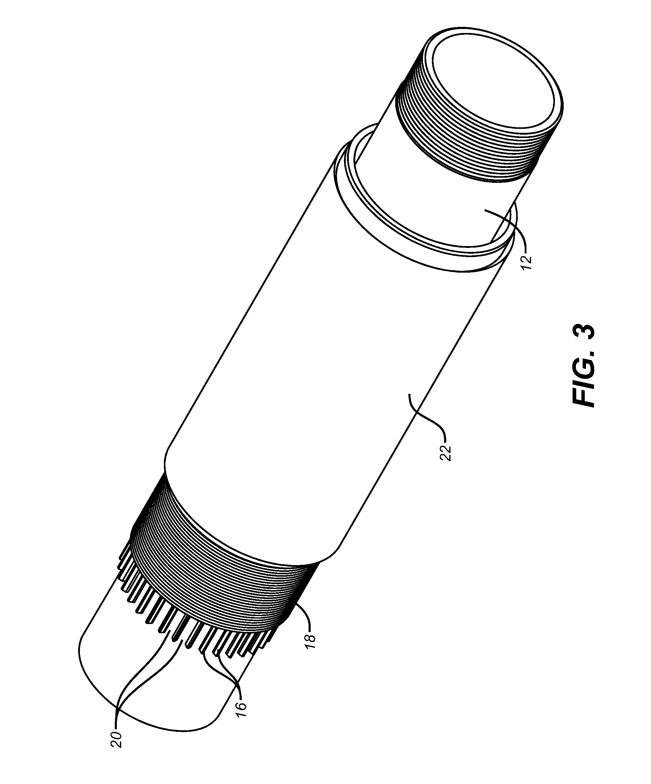
[0016]A screen module 10 is shown in FIGS. 1-3. It has a solid base pipe 12 that defines a through passage 14. A series of parallel ribs 16 retain a wire wrap screen 18 that overlays the ribs 16 creating parallel passages 20 that go under the screen 18. While one style of screen 18 is illustrated, those skilled in the art will appreciate that other types of screens can be used depending on the requirements of the specific application. For clarity, only one end ring 22 is illustrated that is welded at 24 to the right of the screen 18. FIGS. 8a-8b show a complete screen module 10 illustrating the symmetry of the structure by using end ring 26 welded at 28 to screen 18. FIG. 2 illustrates a section view through the end ring 22 showing passages 30 which preferably are in alignment with passages 20 between the rib wires 16. Passages 30 in the aggregate can have different cross sectional flow areas in different modules to serve as inflow control devices for flow balancing among modules 10...


PUM

PropertyMeasurementUnit
diameteraaaaaaaaaa
sizeaaaaaaaaaa
dimensionaaaaaaaaaa

Abstract

A modular screen system allows connection of screens using couplings that connect the annular space in each module between the screen material and the base pipe. A series of connected screens and couplings feed into a single valve to control the flow through many screens. The valve is preferably located in a coupling and the passages through the coupling or the screen can also accommodate instrumentation to detect, store or transmit well data or flows through the various screen modules.

Description

FIELD OF THE INVENTION[0001]The field of the invention is screen assemblies that span multiple zones and more particularly modular screen components that can be assembled with couplings where the couplings can control flow through screens in a given zone.BACKGROUND OF THE INVENTION[0002]In completions that span multiple zones, an array of screens is frequently positioned in each of the zones. The zones are typically isolated with packers and are individually fractured and gravel packed generally in a downhole to uphole direction. In the past a given zone could be long enough to warrant using multiple screen sections. Typically, each of these screen sections had a base pipe under the screen material and a valve, typically a sliding sleeve, associated with each screen section. The annular space between the screen material and the base pipe for each screen section was sealed at opposed ends on a given screen section and the only access into the base pipe for flow of production to the s...

Claims


Application Information

Patent Timeline
Patent Type & Authority Applications(United States)
IPC IPC(8): E21B43/08E21B34/06
CPCE21B34/14E21B2034/007E21B43/14E21B43/08E21B2200/06
Inventor HAMMER, AARON C.CLEM, NICHOLAS J.O'MALLEY, EDWARD J.
Owner BAKER HUGHES INC
Why Eureka
Try Eureka