Quick insertion lamp assembly

a technology of lamp assembly and light source, which is applied in the direction of light source semiconductor devices, coupling device connections, lighting and heating apparatus, etc., can solve the problems of requiring a relatively significant amount of time and the type of interconnection of light source to sock

Active Publication Date: 2011-02-03
TYCO ELECTRONICS LOGISTICS AG (CH)
View PDF45 Cites 49 Cited by
  • Summary
  • Abstract
  • Description
  • Claims
  • Application Information

AI Technical Summary

Problems solved by technology

The screw-type interconnection of the light source to the socket is not without problems.
Failure to fully screw the light source into the socket may result in the light source being mechanically secured to the socket without the light source being electrically coupled with the socket.
On the other hand, fully screwing the light source into the socket may require multiple complete rotations of the light source into the socket and may require a relatively significant amount of time.

Method used


Image

  • Quick insertion lamp assembly
  • Quick insertion lamp assembly
  • Quick insertion lamp assembly

Examples


Embodiment Construction

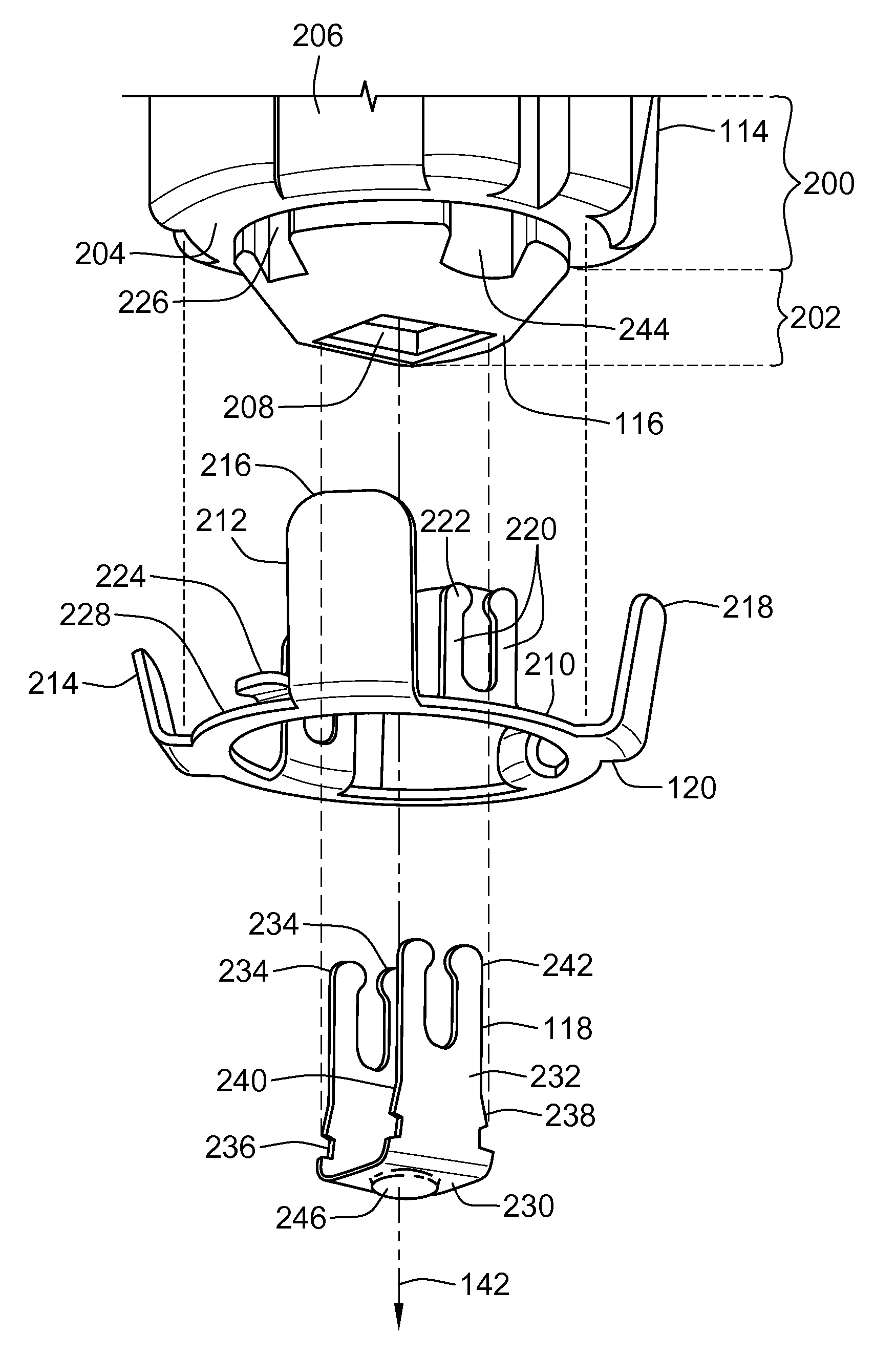
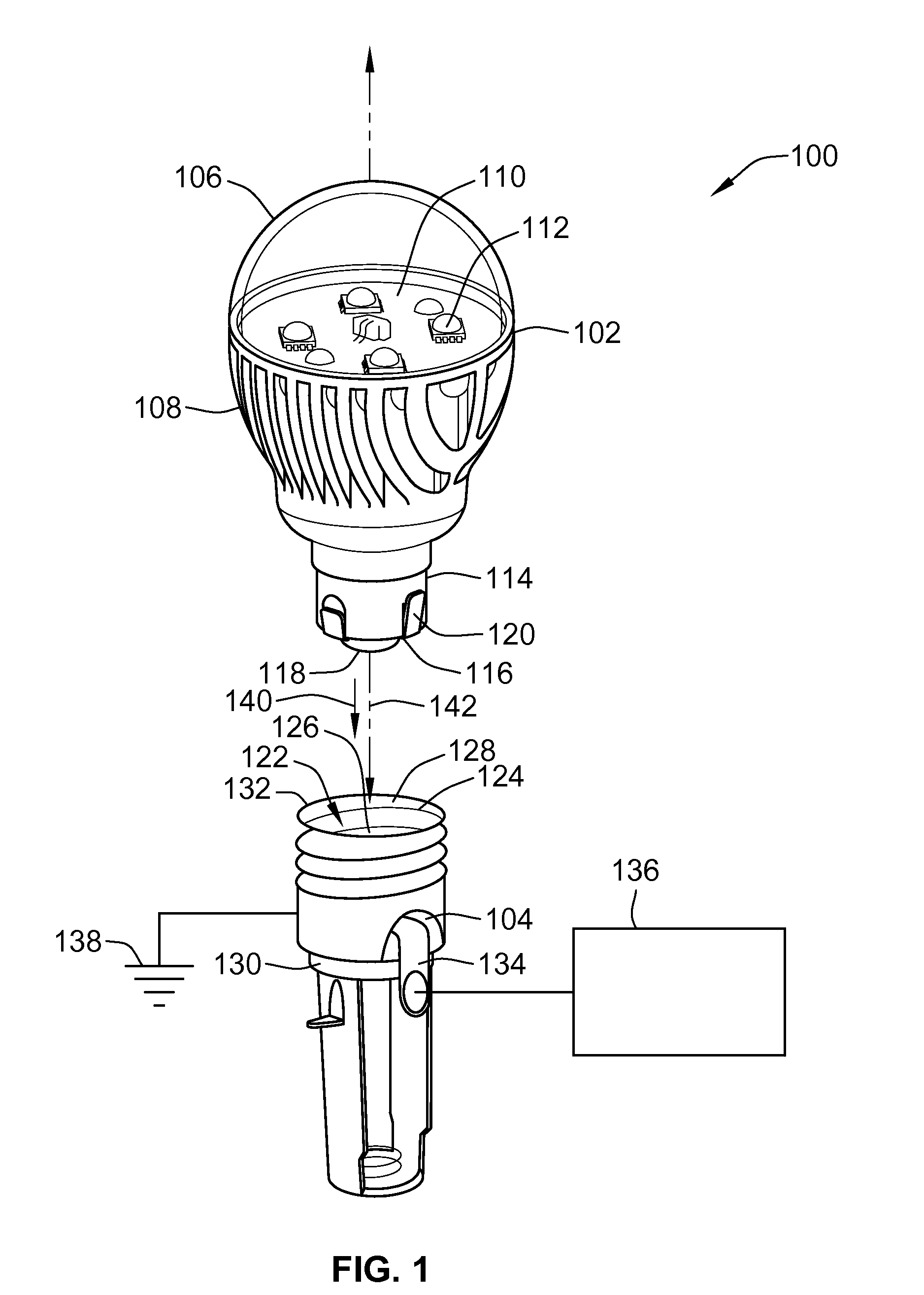
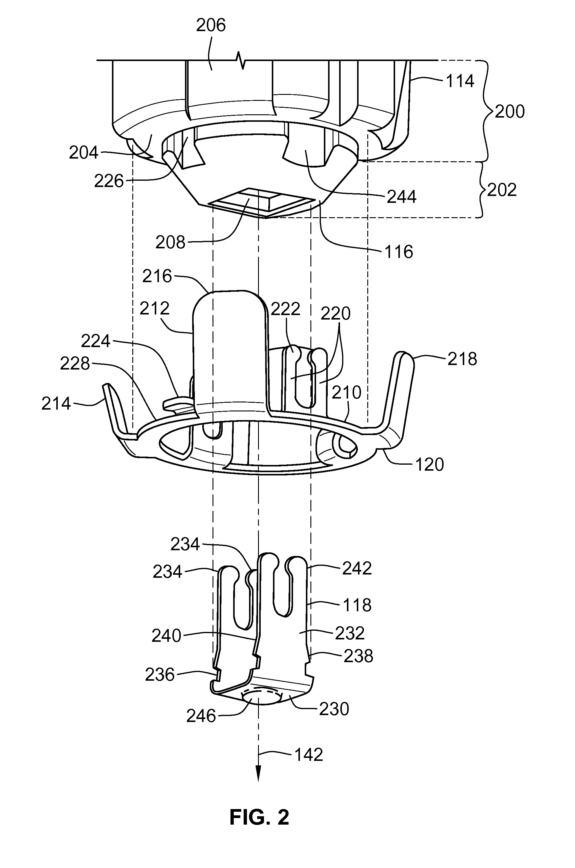
FIG. 1 is a perspective view of a lighting system 100 in accordance with one embodiment of the present disclosure. The lighting system 100 includes a lamp assembly 102 that mates with a socket 104. The lamp assembly 102 generates light from electric power or current that is received from the socket 104. In the illustrated embodiment, the lamp assembly 102 is a light emitting diode (LED) lighting device. Alternatively, the lamp assembly 102 may be another type of lighting device, such as an incandescent, halogen, or metal halide lighting device. The lamp assembly 102 includes a light-transmissive lens 106 that is coupled with a heat sink 108. A circuit board 110 is coupled to the heat sink 108 in a location that is proximate to, or slightly below, the interface between the lens 106 and the heat sink 108. By way of example only, the circuit board 110 may be a metal clad printed circuit board or an FR4 circuit board. Several light sources 112 are mounted to the circuit board 110. In th...


PUM


Abstract

A lamp assembly includes a light source, a contact base, a center contact and an outer contact. The contact base extends from a lower end to an upper end along a center axis. The upper end is interconnected with the light source and the lower end is configured to be received in a socket to mate the contact base with the socket. The center contact is disposed proximate the lower end of the contact base and is electronically coupled with the light source. The outer contact includes a ring body and an elongated contact line. The ring body encircles the center contact proximate the lower end of the contact base. The center contact and the outer contact are mechanically and electrically coupled with the socket and electrically join the light source with an electric ground reference.

Description

BACKGROUND OF THE INVENTIONThe subject matter herein relates generally to lighting systems, and more particularly, to lamp assemblies.Many known lighting systems include light sources that have an Edison-style base that is screwed into a socket. For example, the light sources may include a threaded end that is screwed into a socket to electrically couple the light source with the socket. The socket is joined with a source of electric current and a ground reference to supply power to the light source such that the light source may generate light. The screwing of the light sources into the socket typically requires several complete rotations of the light source relative to the socket to ensure that the light source is both mechanically secured to the socket and electrically coupled with the socket.The screw-type interconnection of the light source to the socket is not without problems. Failure to fully screw the light source into the socket may result in the light source being mechani...

Claims


Application Information

Patent Timeline
Patent Type & Authority Applications(United States)
IPC IPC(8): H01R13/52
CPCF21Y2101/02H01J5/50H01R33/22F21V19/003F21V23/002F21V23/006F21V3/00F21K9/1355F21K9/23F21K9/238F21Y2115/10F21V5/04
Inventor MOSTOLLER, MATTHEW EDWARDDAILY, CHRISTOPHER GEORGE
Owner TYCO ELECTRONICS LOGISTICS AG (CH)
Why Eureka
Try Eureka