Dipper Stick with Implement Coupling Means

a technology of coupling means and dippers, which is applied in the direction of couplings, manufacturing tools, mechanical machines/dredgers, etc., can solve the problems of decreasing the payload and the productivity of the machin

Active Publication Date: 2011-02-10
ROCKLAND
View PDF3 Cites 7 Cited by
  • Summary
  • Abstract
  • Description
  • Claims
  • Application Information

AI Technical Summary

Benefits of technology

[0003]The aforementioned and other objects of the present invention are achieved by providing a first assembly including a pair for jaw members pivotally connected to a dipper stick and cooperable upon pivotal movement thereof to selectively grip and release one of the mounting pins of an implement, and means for selectively pivoting such jaw members in opposite directions to effect such grip and release of such mounting pin; and second and third assemblies each including a pair of jaw members pivotally connected to one of the tilt links of the machine and cooperable upon pivotal movement thereof to selectively grip and release the other of the mounting pins of the implement, and means for selectively pivoting the jaw members in opposite directions to effect such grip and release of the other of the mounting pins. In one embodiment of the invention, in each of such assemblies, a fluid actuated cylinder assembly is used to provide a reciprocating action, and a suitable linkage is provided for translating the reciprocating, linear motion of the rod member of the cylinder assembly to pivotal motion of the jaw members to provide the gripping and releasing action. In another embodiment of the invention, a spring is provided for biasing the jaws in an open position and a caroming action is utilized to urge the jaws into a closed position. It further is contemplated that such assemblies may be produced as kits and / or complete assemblies and retrofitted on machines having commercially available dipper sticks and tilt links.

Problems solved by technology

They normally are large, bulky and heavy, unduly adding excess weight to the front end of the machine and correspondingly decreasing the payload and productivity of the machine.

Method used


Image

  • Dipper Stick with Implement Coupling Means
  • Dipper Stick with Implement Coupling Means
  • Dipper Stick with Implement Coupling Means

Examples


Embodiment Construction

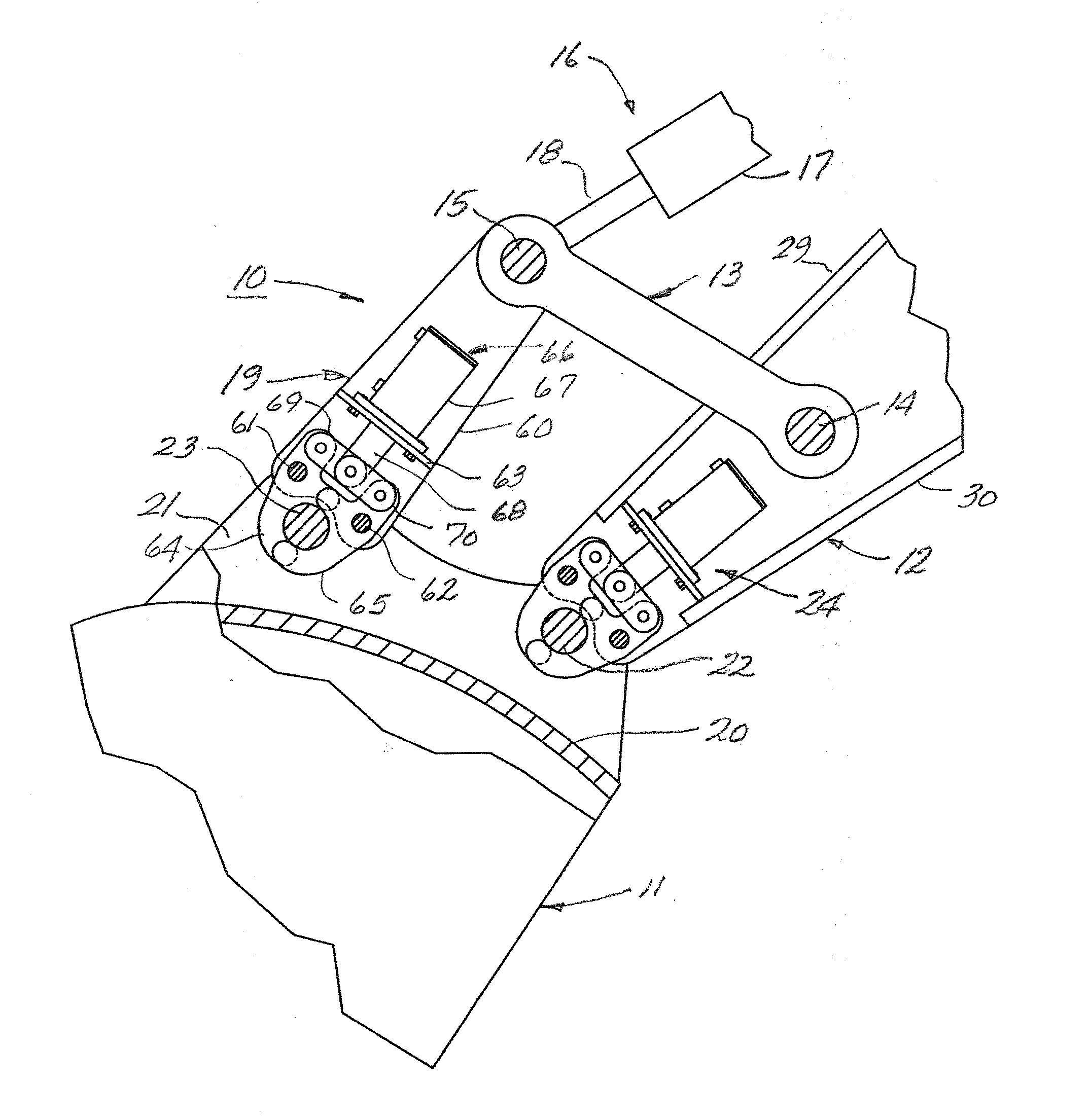
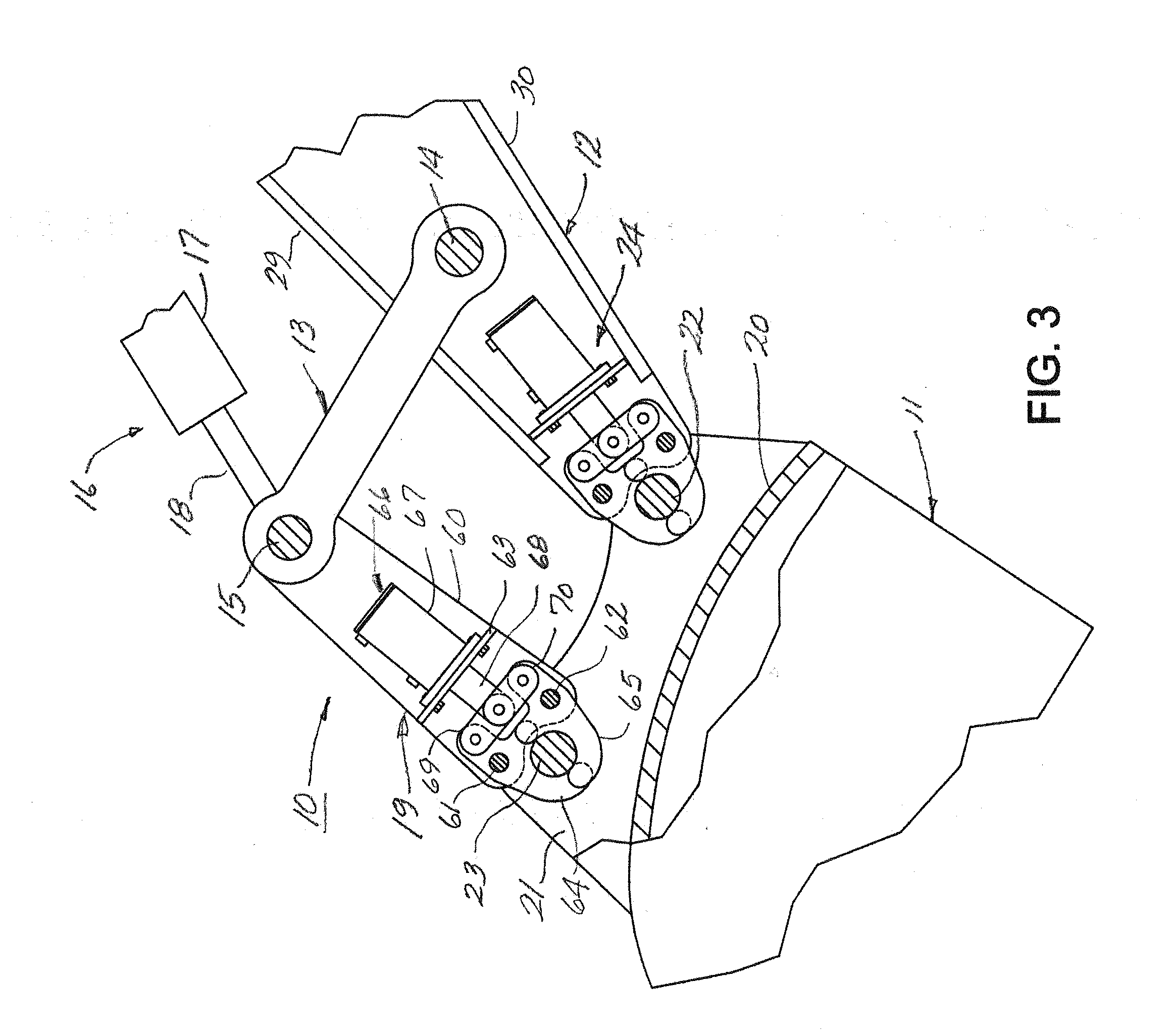
[0016]Referring to FIG. 3 of the drawings, there is partially illustrated a front end assembly 10 of a machine and an implement 11 detachably connected to such front end assembly. The machine is of a conventional construction including a main frame supported crawler or wheel units, an upper frame and cab mounted on the support frame and possibly rotatable thereon, a boom mounted on the main or upper frame, a fluid actuated cylinder assembly operatively interconnecting such boom and a frame of the machine for raising and lowering it and front end assembly 10 operatively connected to the boom. The front end assembly is operatively connected to the boom end and includes a dipper stick 12 pivotally connected at an end thereof to the free end of the boom, a fluid actuated cylinder assembly operatively interconnecting the dipper stick and boom for pivotally displacing the dipper stick relative to the boom, a pair of support links 13, 13 pivotally connected at one set of ends to a connecti...


PUM


Abstract

An assembly for detachably connecting an implement having a pair of mounting pins to a machine provided with a dipper stick and a pair of tilt links operatively connected to the dipper stick, comprising a first assembly including a pair of jaw members pivotally connected to the dipper stick and cooperable upon pivotal movement thereof to selectively grip and release one of the mounting pins, and means for selectively pivoting the jaw members in opposite directions to effect such grip and release of the one of the mounting pins; and second and third assemblies each including a pair of jaw members pivotally connected to one of the tilt links and cooperable upon pivotal movement thereof to selectively grip and release the other of the mounting pins, and means for selectively pivoting the jaw members in opposite directions to effect such grip and release of the other of the mounting pins.

Description

[0001]This invention relates to assemblies mountable on machines having front end assemblies including a dipper stick and tilt links for detachably coupling various implements thereto.BACKGROUND OF THE INVENTION[0002]In various industries including the construction, mining, land clearing and other industries, in an effort to improve productivity, it has been the practice to use various types of couplers for detachably mounting a number of different implements on machines for performing different work functions. Typically, such couplers have consisted of devices mountable on the dipper stick and tilt links of the machine, and connectable to mounting pins provided on the implements. They normally are large, bulky and heavy, unduly adding excess weight to the front end of the machine and correspondingly decreasing the payload and productivity of the machine. Accordingly, it is the principal object of this invention to provide an improved coupling arrangement for machines equipped with ...

Claims


Application Information

Patent Timeline
Patent Type & Authority Applications(United States)
IPC IPC(8): E02F3/96
CPCE02F3/3618Y10T403/59E02F3/3663E02F3/3636
Inventor GERAGHTY, WILLIAM F.
Owner ROCKLAND
Why Eureka
Try Eureka