Expandable intervertebral implant

a technology of intervertebral implants and expandable implants, which is applied in the field of intervertebral implants, can solve the problems of disc height loss, facet and nerve impingement,

Active Publication Date: 2011-02-10
DEPUY SYNTHES PROD INC
View PDF12 Cites 413 Cited by
  • Summary
  • Abstract
  • Description
  • Claims
  • Application Information

AI Technical Summary

Benefits of technology

[0007]Certain embodiments are directed to an expandable intervertebral implant for insertion into an intervertebral disc space and expandable from an initial position to an expanded position. The expandable intervertebral implant includes a linkage that includes a plurality of links connected in a longitudinal direction. Each link includes an outer sleeve having a first outer sleeve portion and a second outer sleeve portion that is movable with respect to the first outer sleeve portion. The second outer sleeve portion defines a first engagement surface that is sloped with respect to the longitudinal direction. Each link further includes an inner core disposed between the first and second outer sleeve portions. The inner core defines a second engagement surface that is sloped with respect to the longitudinal direction, wherein the second engagement surface abuts the first engagement surface. Relative movement between the inner core and the second outer sleeve portion along the longitudinal direction causes the first engagement surface to ride along the second engagement surface, thereby causing the second outer sleeve portion to deflect away from the first outer sleeve portion in a direction substantially perpendicular to the longitudinal direction.

Problems solved by technology

Degenerative disc disease or degeneration of a vertebral body often results in a loss of disc height, which in turn can cause facet and nerve impingement, among other things.

Method used


Image

  • Expandable intervertebral implant
  • Expandable intervertebral implant
  • Expandable intervertebral implant

Examples


Embodiment Construction

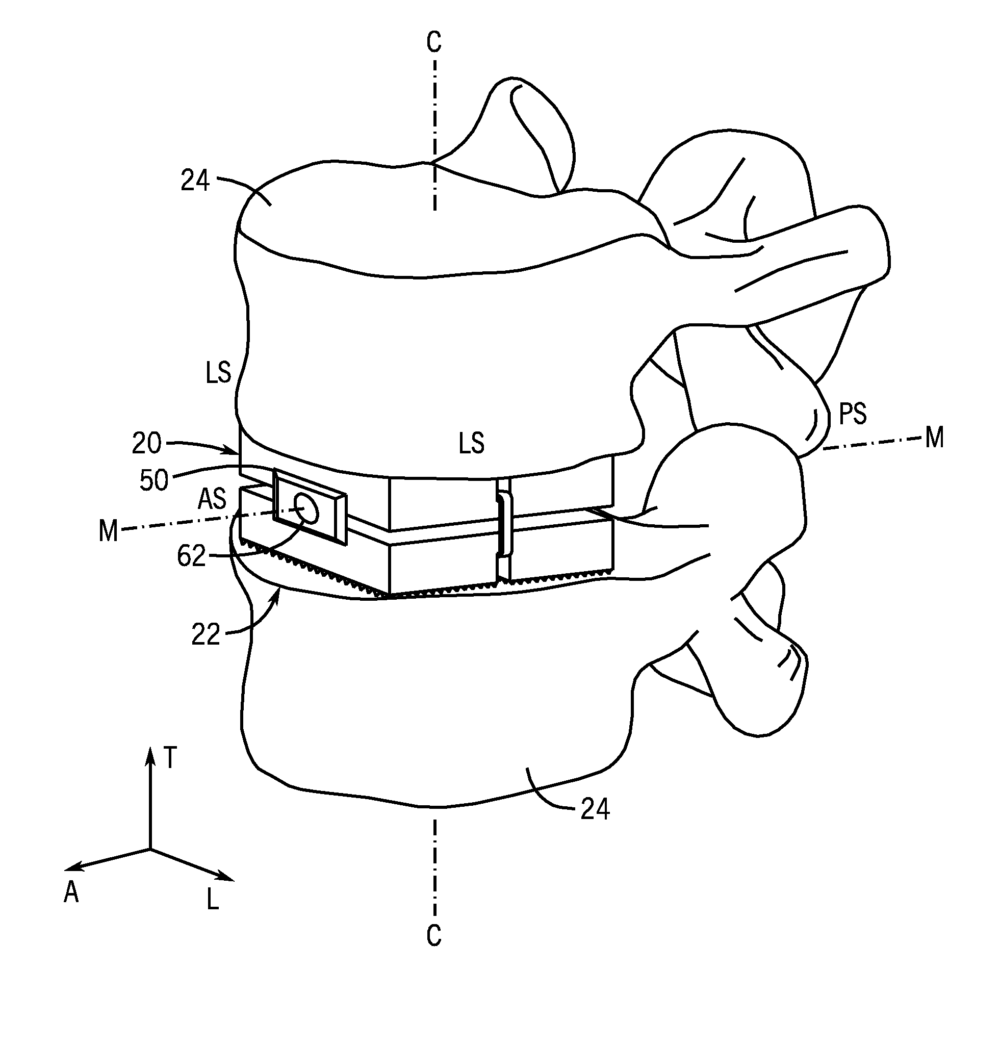
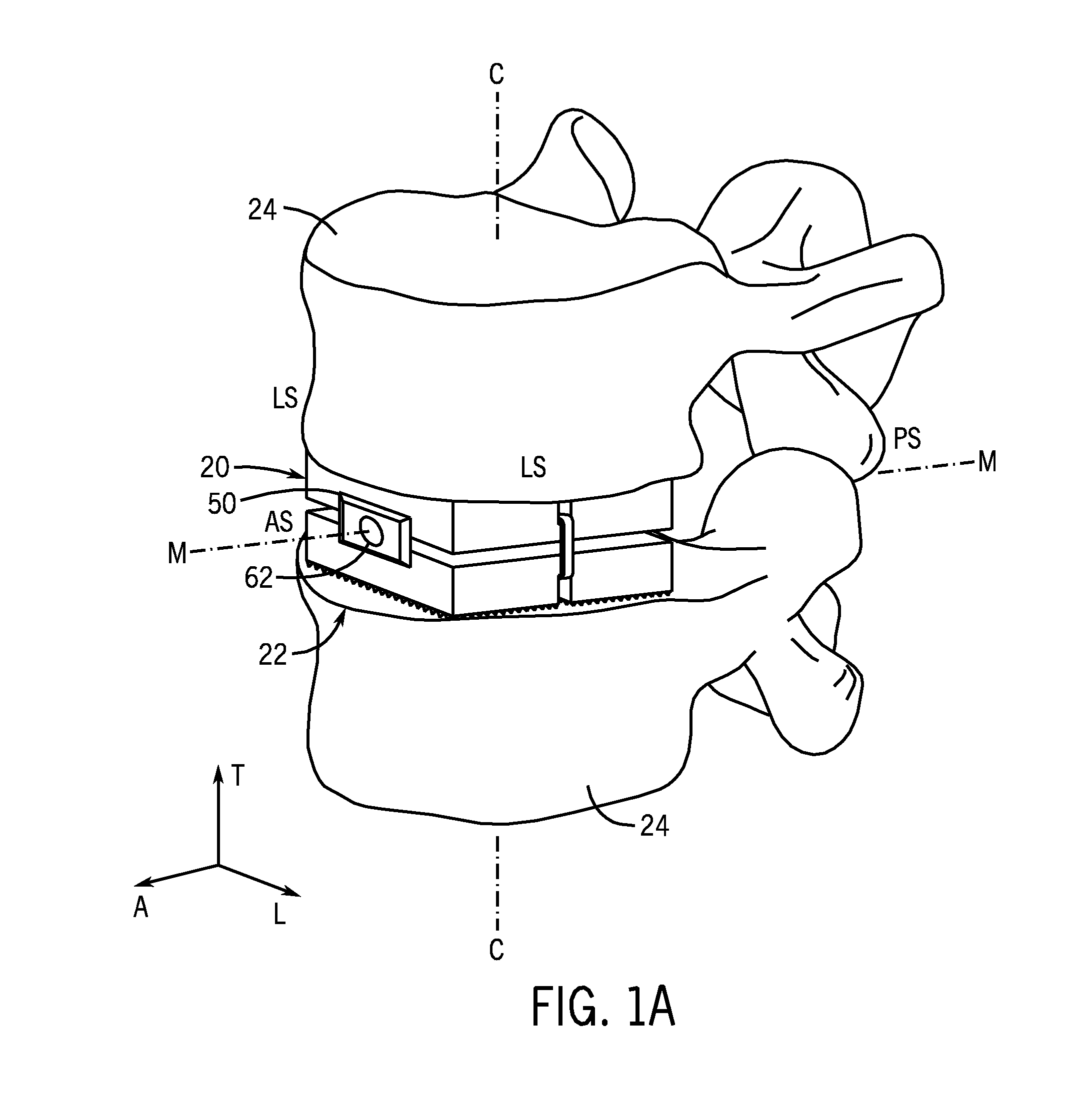
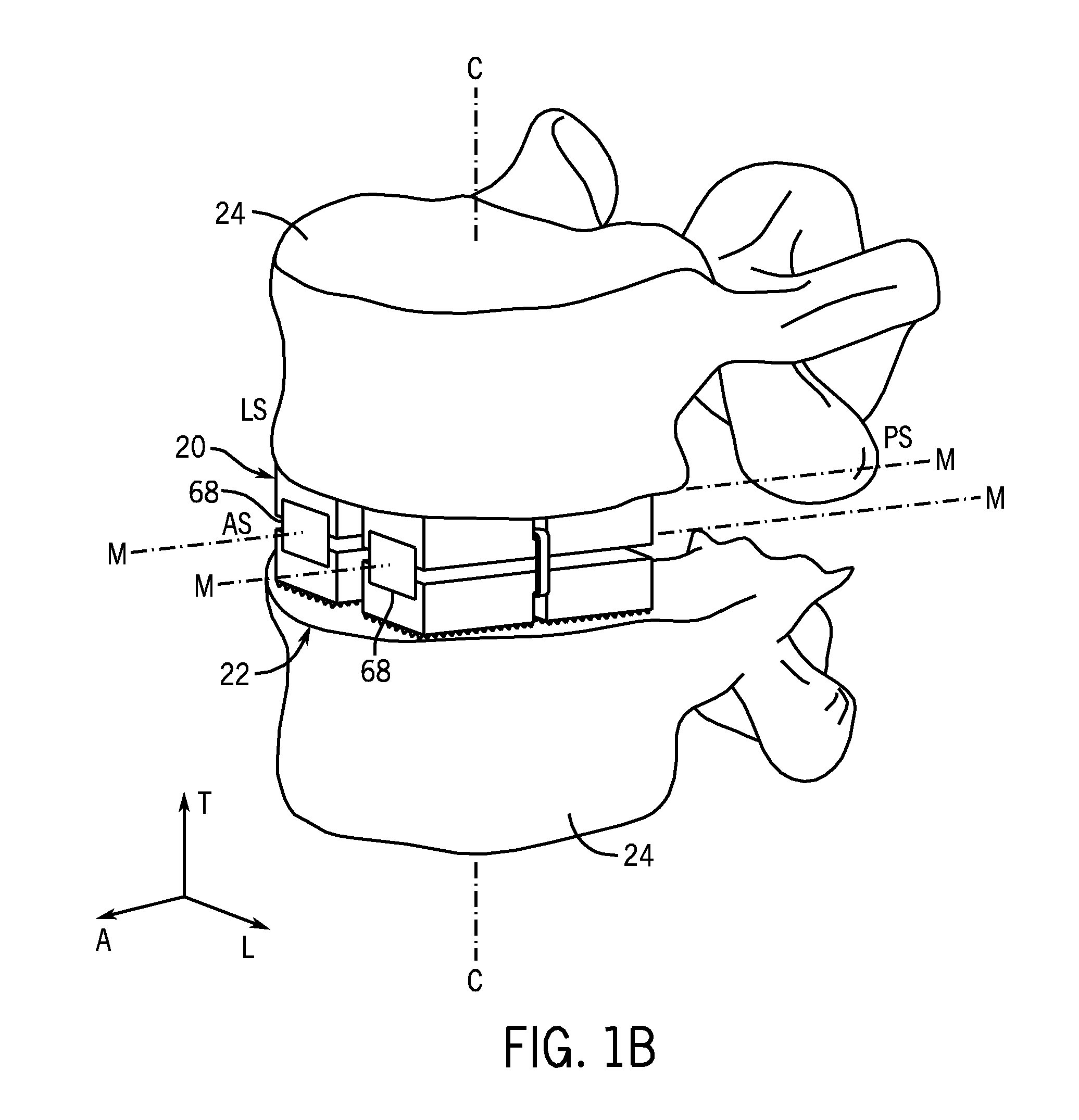
[0047]Certain terminology is used in the following description for convenience only and is not limiting. The words “right”, “left”, “lower” and “upper” designate directions in the drawings to which reference is made. The words “inwardly” or “distally” and “outwardly” or “proximally” refer to directions toward and away from, respectively, the geometric center of the expandable implant, instruments and related parts thereof. The words, “anterior”, “posterior”, “superior,”“inferior” and related words and / or phrases designate preferred positions and orientations in the human body to which reference is made and are not meant to be limiting. The terminology includes the above-listed words, derivatives thereof and words of similar import.

[0048]Referring to FIG. 1A, an expandable intervertebral implant 20 is shown installed into an intervertebral disc space 22 defined by a pair of adjacent, or neighboring, upper and lower vertebrae 24. The expandable intervertebral implant 20 can be configu...


PUM


Abstract

An expandable intervertebral implant (20) is provided for insertion into an intervertebral space defined by adjacent vertebrae. The expandable intervertebral implant includes a pair of outer sleeve portions (30A, 30B) and an inner core (50) disposed between the outer sleeve portions. Movement of the inner core relative to the outer sleeve portions causes the outers sleeve portions to deflect away from each other, thereby engaging the expandable intervertebral implant with the vertebrae and adjusting the height of the intervertebral space.

Description

CROSS-REFERENCE TO RELATED APPLICATIONS[0001]This application claims the benefit of U.S. Provisional Application Ser. No. 61 / 042,724, filed on Apr. 5, 2008, the disclosure of which is hereby incorporated by reference as if set forth in its entirety herein.FIELD OF THE INVENTION[0002]This disclosure relates generally to intervertebral implants, and in particular relates to an intervertebral implant that can expand to create a desired spacing and / or angular orientation of adjacent vertebrae.BACKGROUND OF THE INVENTION[0003]Degenerative disc disease or degeneration of a vertebral body often results in a loss of disc height, which in turn can cause facet and nerve impingement, among other things. One standard of care is to replace the damaged intervertebral disc with an intervertebral implant or a damaged portion or an entire vertebral body with an intervertebral implant.[0004]Thus, an intervertebral implant may be inserted into the intervertebral disc space of two adjacent vertebral bo...

Claims


Application Information

Patent Timeline
Patent Type & Authority Applications(United States)
IPC IPC(8): A61F2/44
CPCA61F2/442A61F2310/00023A61F2/4611A61F2002/2835A61F2002/30462A61F2002/30471A61F2002/30495A61F2002/305A61F2002/3052A61F2002/30538A61F2002/3055A61F2002/30551A61F2002/30579A61F2002/30616A61F2002/30841A61F2002/30884A61F2002/4415A61F2002/448A61F2002/4627A61F2002/4628A61F2220/0025A61F2220/0075A61F2220/0091A61F2250/0006A61F2/447A61F2002/30601A61F2002/30405A61F2002/30537A61F2002/4485A61F2/4425A61F2002/443
Inventor CAIN, CHRISTOPHER MARDEN JOHN
Owner DEPUY SYNTHES PROD INC
Why Eureka
Try Eureka