Electronic device with detachable plug capable of changing plugging direction

a technology of detachable plugs and electrical devices, which is applied in the direction of electrical devices, electrical discharge tubes, coupling device connections, etc., can solve the problems of difficulty in plugging or pulling out power converters onto or from sockets, and the inability to further utilize socket holes, so as to achieve better space utilization

Active Publication Date: 2011-02-17
DELTA ELECTRONICS INC
View PDF3 Cites 18 Cited by
  • Summary
  • Abstract
  • Description
  • Claims
  • Application Information

AI Technical Summary

Benefits of technology

[0007]It is an object of the present invention to provide an electronic device with a detachable plug to enable the user to choose the assembling direction of the plug, so that the plugging direction of the electronic device can be changed according to different requirements so as to make the electronic device have a better space utilization when plugging onto a socket.
[0008]It is another object of the present invention to provide an electronic device with a detachable plug, wherein the number and the shapes of the conductive terminals of the plug can be varied to adapt to different socket standards to increase the practicability of the electronic device.

Problems solved by technology

Since the main body of the power converter has certain volume, when the power converter is plugged into a wall socket or a socket of an extension cable, the power converter may interfere the objects around the socket due to the plugging direction of the power converter, which makes it difficult to plug or pull out the power converter onto or from the socket.
Under some conditions, the rest holes on the socket may be obstructed by the power converter plugged onto the socket, which causes those socket holes cannot be further utilized.

Method used


Image

  • Electronic device with detachable plug capable of changing plugging direction
  • Electronic device with detachable plug capable of changing plugging direction
  • Electronic device with detachable plug capable of changing plugging direction

Examples


Embodiment Construction

[0020]The present invention will now be described more specifically with reference to the following embodiments. It is to be noted that the following descriptions of preferred embodiments of this invention are presented herein for purpose of illustration and description only. It is not intended to be exhaustive or to be limited to the precise form disclosed.

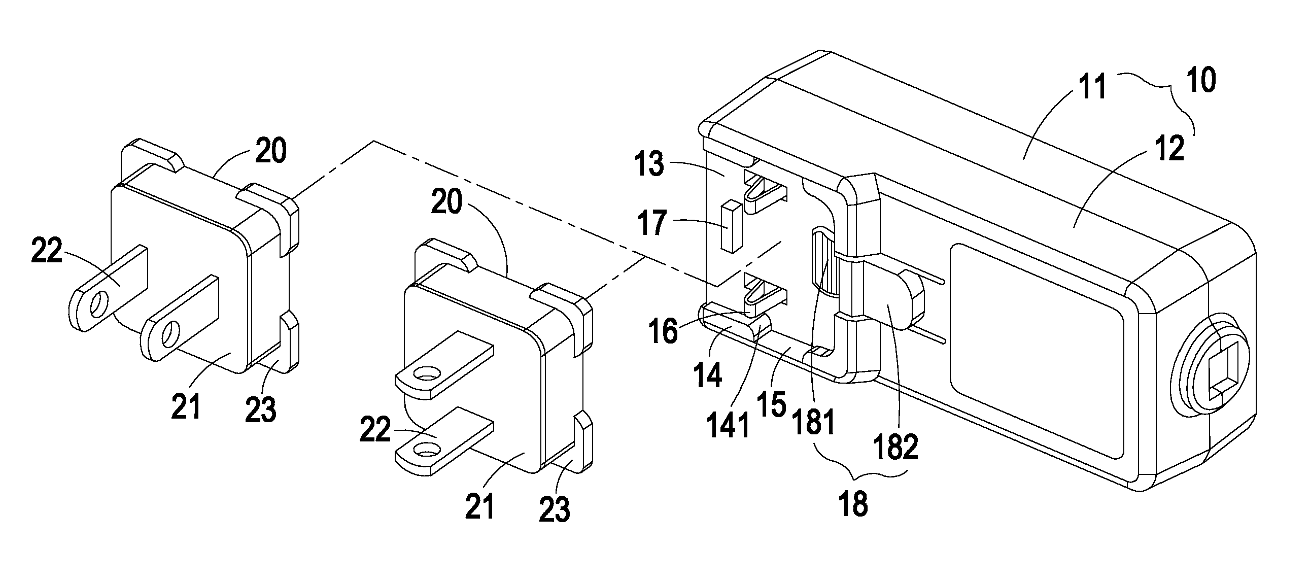
[0021]The present invention relates to an electronic device with a detachable plug capable of changing plugging direction. The present techniques are illustrated with the following embodiments for a power converter, such as adapter and charger, but the electronic device that is applicable to the present techniques is not limited to the power converter. Any electronic device that is applicable to the following techniques is incorporated herein for reference.

[0022]FIG. 1 is a schematic diagram showing the electronic device with a detachable plug capable of changing plugging direction according to a first preferred embodiment of the...


PUM


Abstract

An electronic device with a detachable plug capable of changing plugging direction is disclosed. The electronic device comprises a main body and a plug. The main body has a plug-receiving portion, and the plug-receiving portion comprises at least two conducting pieces. The plug has a plug body and at least two conductive terminals. The plug body comprises four trenches disposed at a bottom thereof and arranged as a square. Each of the conductive terminals comprises a plugging portion, a connection portion and an extension portion, wherein the plugging portion is protruded out of a surface of the plug body, and the connection portion and the extension portion are embedded in the plug body and are corresponding to two adjacent trenches, respectively. Thereby, when the plug is assembled on the plug-receiving portion of the main body, the two conducting pieces are respectively received in two opposite trenches and contacted with either the two connection portions or the two extension portions of the two conductive terminals for power conduction.

Description

CROSS-REFERENCE TO RELATED APPLICATIONS[0001]This application claims the benefit of prior U.S. provisional application 61 / 232,980, which is entitled “ELECTRONIC DEVICE WITH DETACHABLE PLUG” and filed Aug. 11, 2009.FIELD OF THE INVENTION[0002]The present invention relates to an electronic device with a detachable plug, and more particularly to an electronic device with a detachable plug capable of changing plugging direction.BACKGROUND OF THE INVENTION[0003]With the progress of technology, various electronic equipments become indispensable tools in our daily life. The power converter functions to convert the commercial AC power into DC power to be utilized by the electronic equipments. For example, the adapter of a notebook, or the charger of a cellphone or a digital camera, is a kind of power converter.[0004]The power converter includes a plug for plugging into a socket to receive the commercial power. Since the international business is well developed and the leisure life quality i...

Claims


Application Information

Patent Timeline
Patent Type & Authority Applications(United States)
IPC IPC(8): H01R27/00H01R33/00
CPCH01R31/06H01R27/00
Inventor HUANG, CHIN-CHU
Owner DELTA ELECTRONICS INC
Why Eureka
Try Eureka