Overhead hoist transport system

Active Publication Date: 2013-03-14
MICRON TECH INC
View PDF4 Cites 12 Cited by
  • Summary
  • Abstract
  • Description
  • Claims
  • Application Information

AI Technical Summary

Benefits of technology

The present invention is a system for transporting wafers using an overhead rail system. The invention improves the efficient use of clean room space and increases the transfer efficiency of semiconductor wafers. The design includes a rail segment that connects to the main track with two lateral tracks, providing better space utilization and efficient wafer transfer. Overall, the invention provides better results compared to previous overhead transport systems and achieves higher efficiency in the production process.

Problems solved by technology

Additionally, as shown in FIG. 1B, in a semi-conductor fab, production tools are move-in / out very often to meet a new process or product need, or in cases where more production tools are needed due to the increase of production, thus the position of the track 1, the OHT rail of the prior art, and the production tool have resulted a waste in space in the clean room, hence the clean room are expanded to meet the needs, likewise increasing the cost.
If the OHT rail in FIG. 1B is replaced by the OHT rail in FIG. 1C, one more production tool may fit in the very limited clean room space, but the shuttle 2 will have to travel a longer distance whenever the shuttle 2 transports the wafers from tool 4 to tool 4′, hence wasting more time in traveling during production stages, resulting a lower transfer efficiency.

Method used


Image

  • Overhead hoist transport system
  • Overhead hoist transport system
  • Overhead hoist transport system

Examples


second implementation example

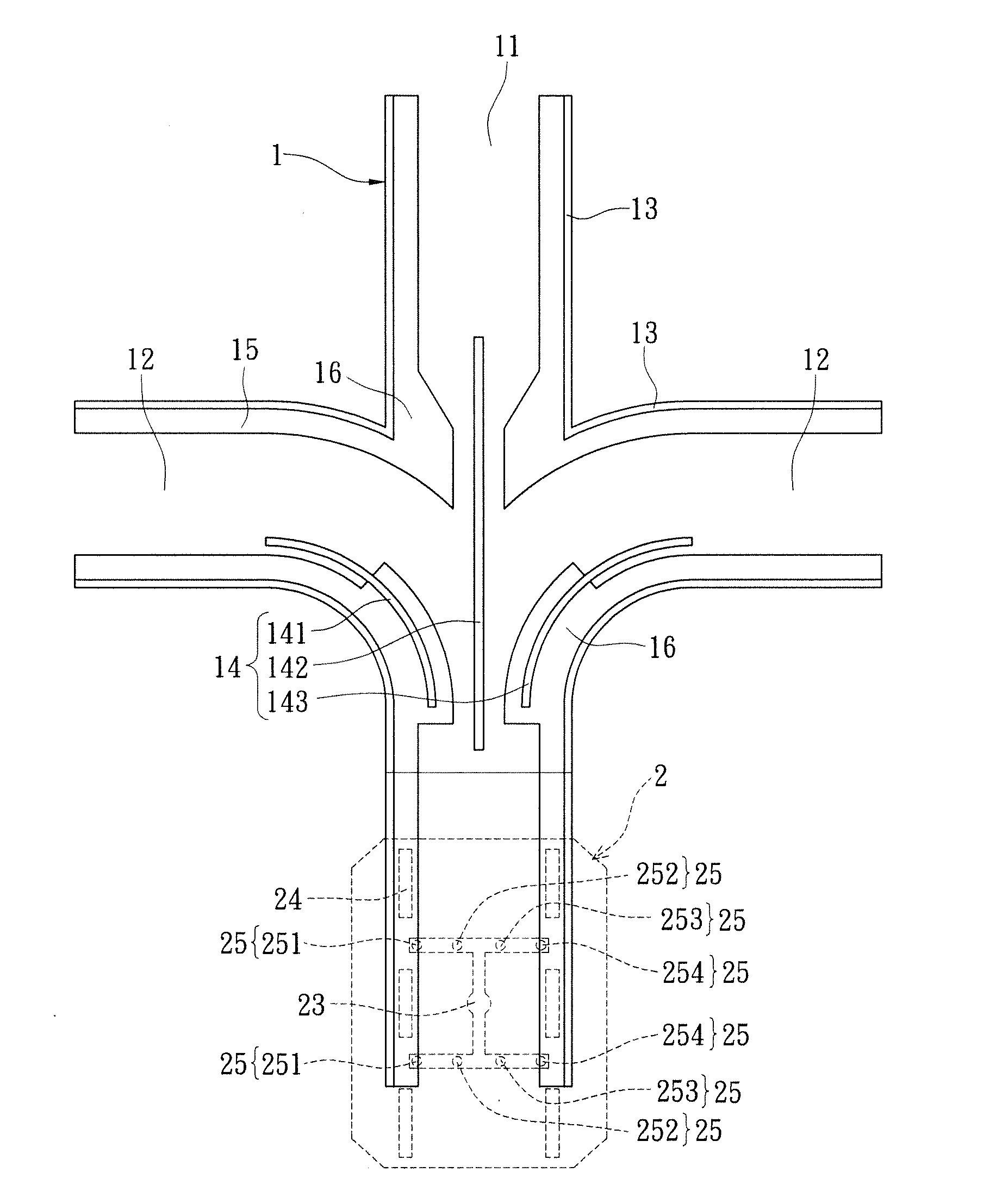
[0032]Referring now to FIG. 8 which is the situation practical application of the present invention. The wafers will be transported to different production units during different stages, using the present invention which comprises a rail segment similar to a tri-directional branch form that can connect the two lateral tracks respectively to the two corresponding sides of the main track 11, allowing the shuttle 2 to transport the wafers to the destination without going round the production tool, improving the transportation efficiency of the wafers.

third implementation example

[0033]Referring now to FIG. 9, another implementation example of the present invention which discloses a situation where tracks and production tools are needed to be positioned in a very limited clean room space. In comparison to the prior arts, the overhead wafer transport system in the present invention acquires a rail segment which is similar to a tri-directional form; the semi-conductor fab can increase a production tool according to its needs. In addition, using the present invention can also achieve better clean room space utilization.

[0034]In conclusion, the present invention, overhead wafer transport system, can achieve higher transfer efficiency, clean room space utilization and a better design of arranging the tracks and the production tools henceforth increase the productivity of the semi-conductor fabs.


PUM


Abstract

An overhead wafer transport system includes an over head transportation (OHT) rail and at least one shuttle. The OHT rail includes a main track and two lateral tracks, each having a hollow transverse cross-section, each lateral track being in corresponding connection with the main track through the two sides thereof, constituting an approximate tri-directional branch form. The shuttle has a track-interface assembly and a docking unit, the track-interface assembly being adapted to travel along the OHT rail. The track-interface assembly being arranged at the junction of the two lateral tracks and the main track, wherein the track-interface assembly is adapted to selectively travel along at least one of the main track and the lateral tracks. Therefore, the overhead wafer transport system can be applied to a clean room with higher transfer efficiency and clean room space utilization.

Description

BACKGROUND OF THE INVENTION[0001]1. Field of the Invention[0002]The present invention relates to overhead hoist transport system; in particular, to overhead hoist wafer transport system.[0003]2. Description of Related Art[0004]Semi-conductor fabrication plant (fabs) usually own production tools to manufacture semi-conductor wafers, for example, processes such as exposure, etching, diffusing and ion implant, grinding through chemical machines or thin film deposition. During the process of manufacturing, the wafers will be transported to different production units (also known as BAY) to undergo corresponding manufacturing process, or remain in the same production unit to undergo different manufacturing process in different stages. Therefore, semi-conductor fabs usually make use of the auto-transportation system to assist in transporting the wafers to different production units throughout different stages of manufacturing.[0005]Please refer to FIG. 1A, which shows a common arrangement ...

Claims


Application Information

Patent Timeline
IPC IPC(8): E01B25/26E01B25/24
CPCH01L21/67733E01B25/22
Inventor CHEN, TSAN-IFANG, WEN-YU
Owner MICRON TECH INC
Why Eureka
Try Eureka