Imaging apparatus

a technology of optical elements and support accuracy, applied in the field of optical apparatuses, can solve the problems of increasing processing load and the inability to avoid the increase in the size of the anti-shake system, and achieve the effects of reducing size, improving drive control performance, and improving the support accuracy of anti-shake optical elements

Inactive Publication Date: 2016-04-28
HOYA CORP
View PDF2 Cites 14 Cited by
  • Summary
  • Abstract
  • Description
  • Claims
  • Application Information

AI Technical Summary

Benefits of technology

[0010]The present invention has been devised in view of the above described problems, and the present invention provides an imaging apparatus equipped with an anti-shake system which performs a spherical swinging operatio...

Problems solved by technology

Additionally, according to the structure disclosed in Patent Literature 3, an increase in size of the anti-shake system cannot be avoided because the entire camera section is driven to perform the spherical swinging operation.
Even if the relative positional ...

Method used


Image

  • Imaging apparatus
  • Imaging apparatus
  • Imaging apparatus

Examples


Embodiment Construction

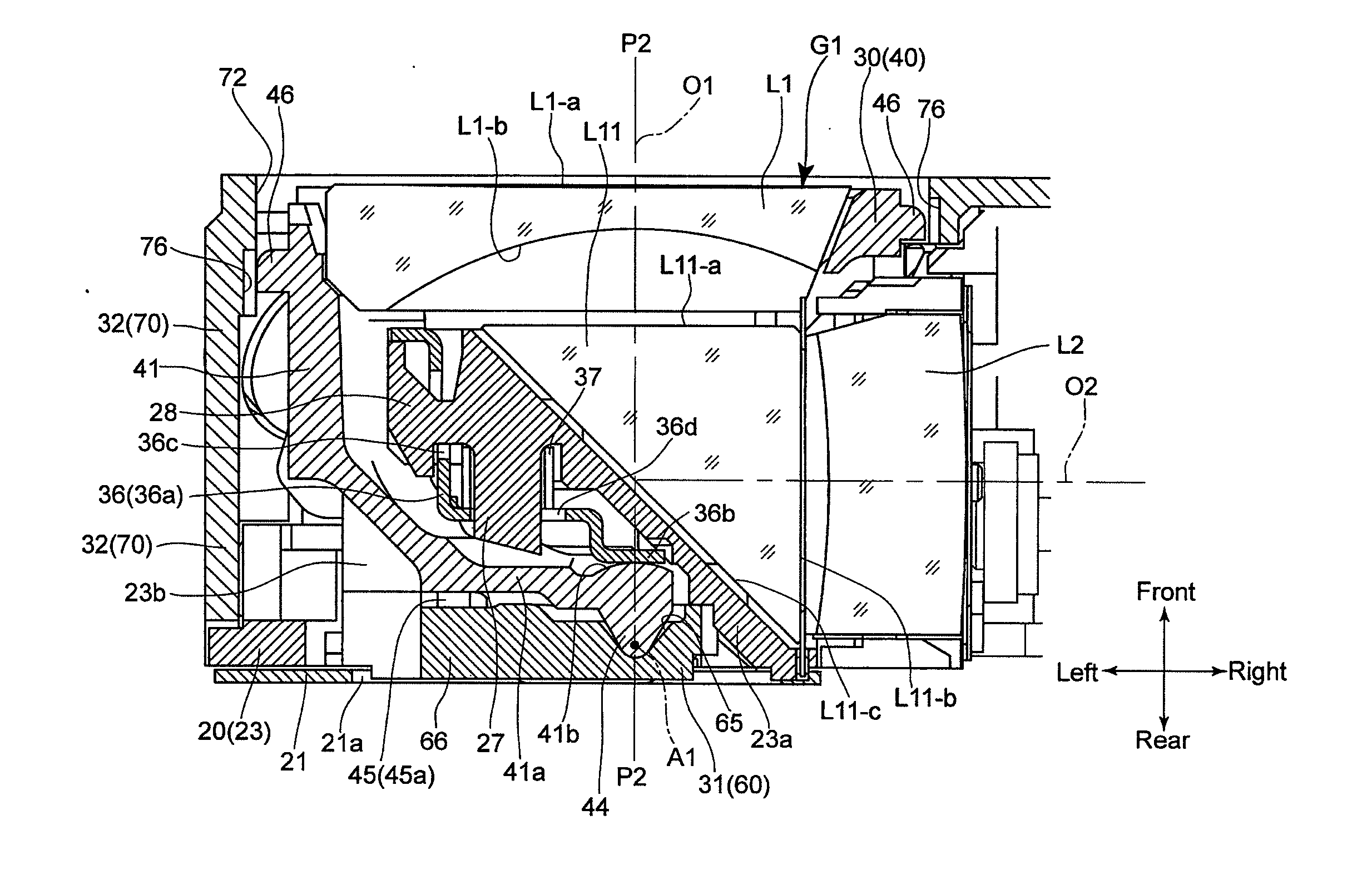
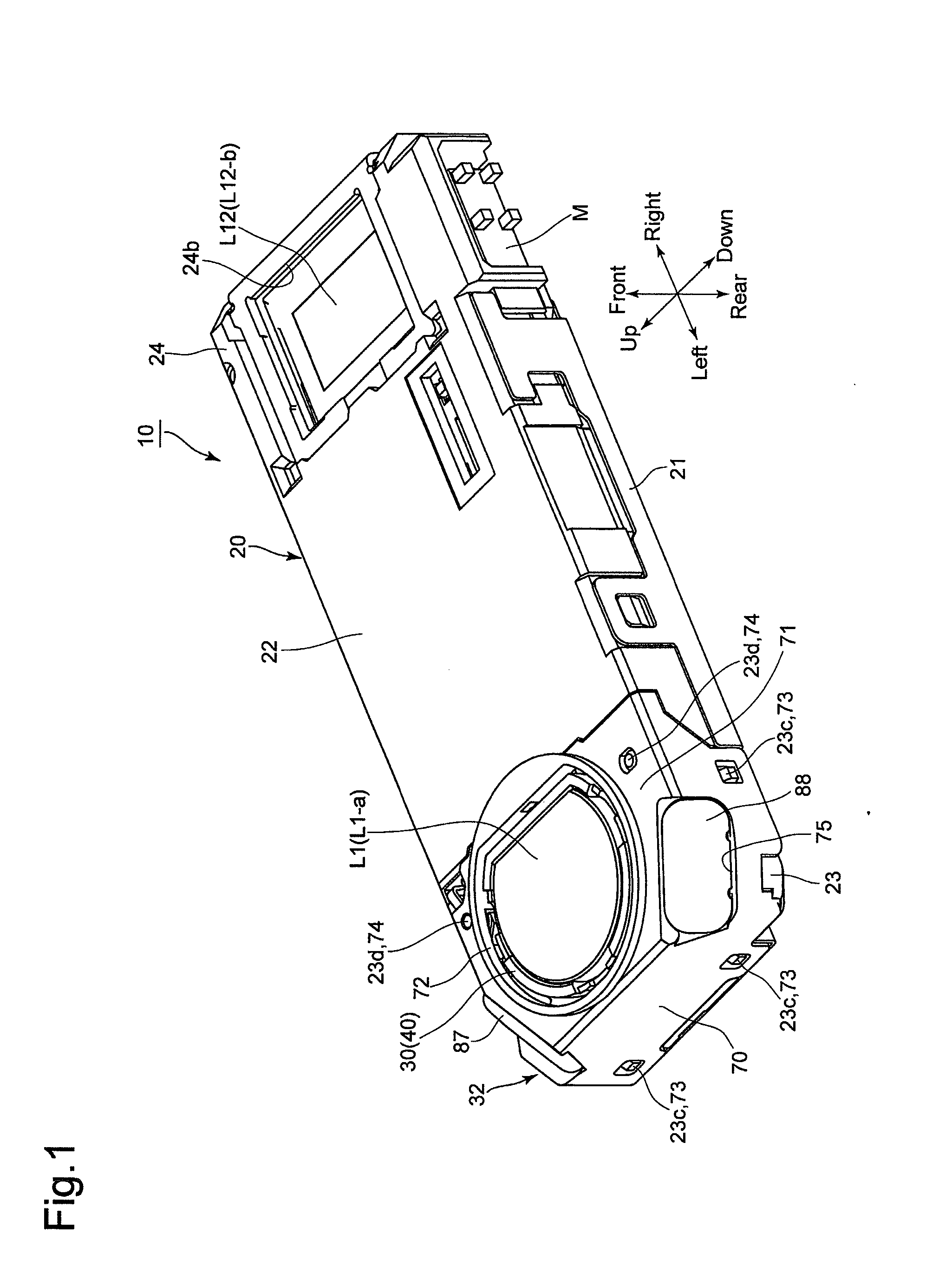
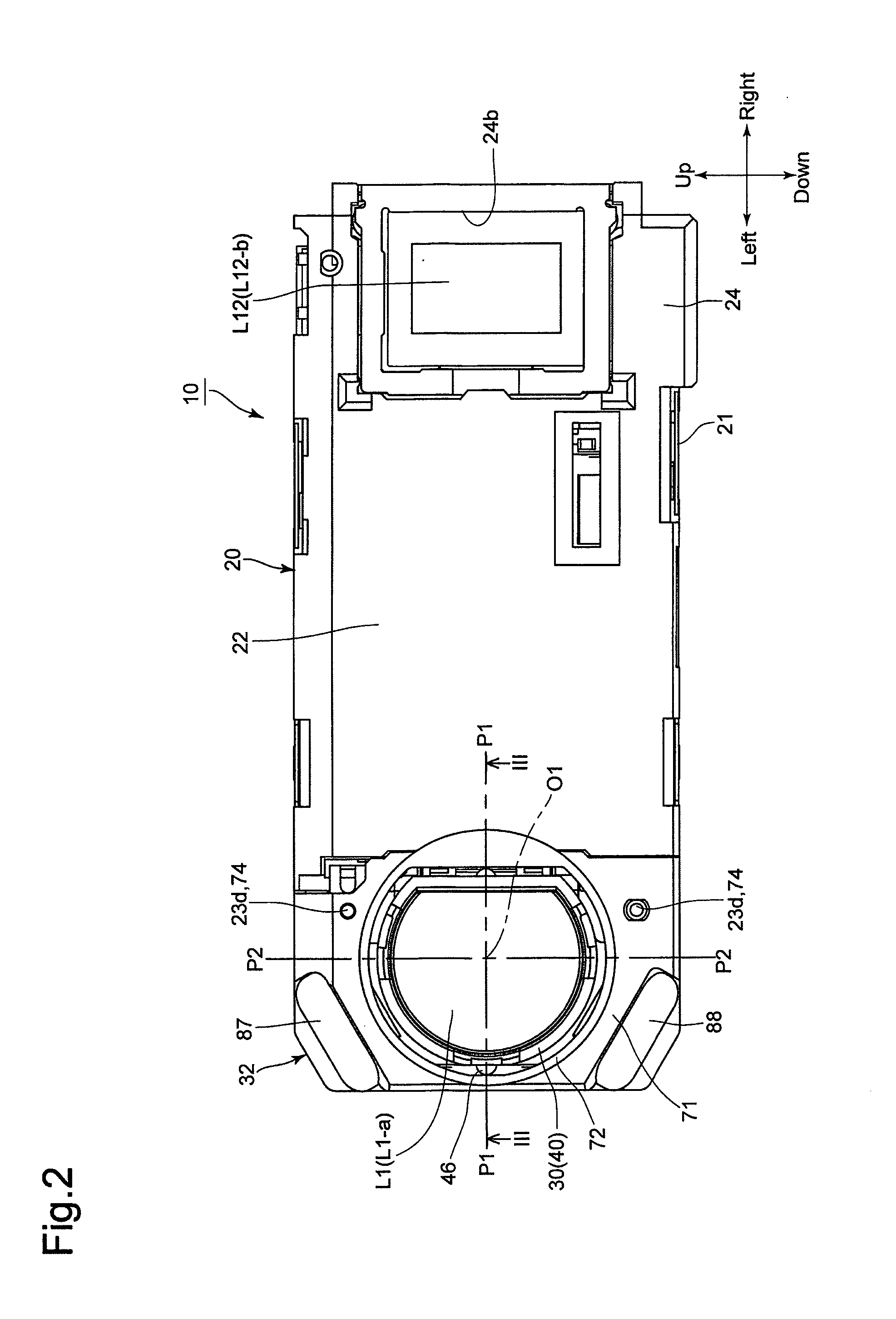
[0059]An embodiment of an imaging unit (imaging apparatus) 10 according to the present invention will be discussed below with reference to FIGS. 1 through 32. In the following descriptions, forward and rearward directions, leftward and rightward directions, and upward and downward directions are determined with reference to the directions of the double-headed arrows shown in the drawings. The object side corresponds to the front side. As shown by the outward appearance of the imaging unit 10 in FIGS. 1 and 2, the imaging unit 10 has a laterally elongated shape which is slim in the forward and rearward directions and elongated in the leftward and rightward directions.

[0060]The imaging unit 10 is provided with an imaging optical system shown in FIG. 32. As shown in FIG. 32, this imaging optical system is provided with a first lens group (front lens group) G1, a second lens group (rear lens group) G2, a third lens group (rear lens group) G3 and a fourth lens group (rear lens group) G4....


PUM


Abstract

An imaging apparatus includes a front lens group, including a reflector element and a front lens element on the object side thereof, and a rear lens group; a support member, fixed to a fixed member that supports the reflector element, including a spherical-swinging operation support positioned behind the reflection surface of the reflector element and supporting a movable member supporting the front lens element to spherically swing about a predetermined point, a rotation preventer preventing the movable member from rotating about the optical axis of the front lens element, a detector supporter, and a mounting portion mounted to the fixed member; an actuator which drives the movable member to spherically swing the movable member in response to vibrations applied to the imaging optical system; a detector detecting positional variations of the movable member; and an adjuster which adjusts the position of the mounting portion relative to the fixed member.

Description

BACKGROUND OF THE INVENTION[0001]1. Field of the Invention[0002]The present invention relates to an imaging apparatus equipped with an anti-shake (image shake correction / image stabilizing / shake reduction) system.[0003]2. Description of the Related Art[0004]In recent years, mobile electronic devices which are designed mainly for taking still / moving photographic images, such as digital cameras (still-video cameras) and digital camcorders (motion-video cameras), and other mobile electronic devices which are designed to be capable of taking such photographic images as a subsidiary function, such as mobile phones equipped with a camera and smart devices (smart phones or tablet computers, etc.) equipped with a camera, have become widespread. There has been a demand for an imaging apparatus which is incorporated in such mobile electronic devices to be equipped with a so-called anti-shake (image shake correction / image stabilizing / shake reduction) system that is designed to reduce image shak...

Claims


Application Information

Patent Timeline
IPC IPC(8): G02B27/64G02B7/02H04N5/225G02B13/00
CPCG02B27/646H04N5/2254G02B7/023G02B13/0065G03B5/00H04N23/6812H04N23/687
Inventor NOMURA, HIROSHIMORINAGA, TAKAHIRO
Owner HOYA CORP
Why Eureka
Try Eureka