Small size gear pump

a gear pump and small technology, applied in the direction of positive displacement liquid engines, piston pumps, liquid fuel engines, etc., can solve the problems of high electric power consumption, insufficient suction efficiency, and system cooling with liquid heat mediums having a high heat exchange capacity, and achieve high space efficiency and mechanical strength

Inactive Publication Date: 2005-02-24
MIYAGI NAOKI +2
View PDF13 Cites 16 Cited by
  • Summary
  • Abstract
  • Description
  • Claims
  • Application Information

AI Technical Summary

Benefits of technology

[0025] According to the embodiments described above, the small size gear pump is provided having high space efficiency without generating a wasted space around the place where it is installed by employing a flat and disc-shaped...

Problems solved by technology

However, the conventional pumps have such draw backs as having a large size, having an insufficient suction efficiency or having high electric power consumption.
As a result, a system which cools with a liquid heat medium having a high heat ex...

Method used


Image

  • Small size gear pump
  • Small size gear pump
  • Small size gear pump

Examples


Embodiment Construction

[0044] An embodiment of the small size gear pump according to the present invention is explained in detail referring to the figures appended.

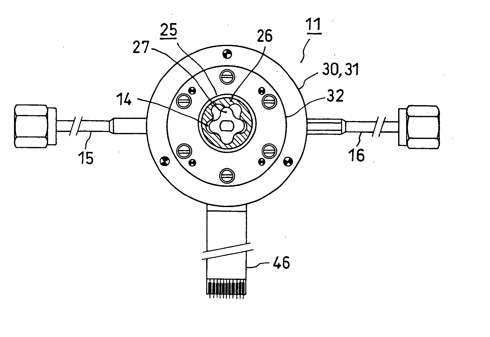
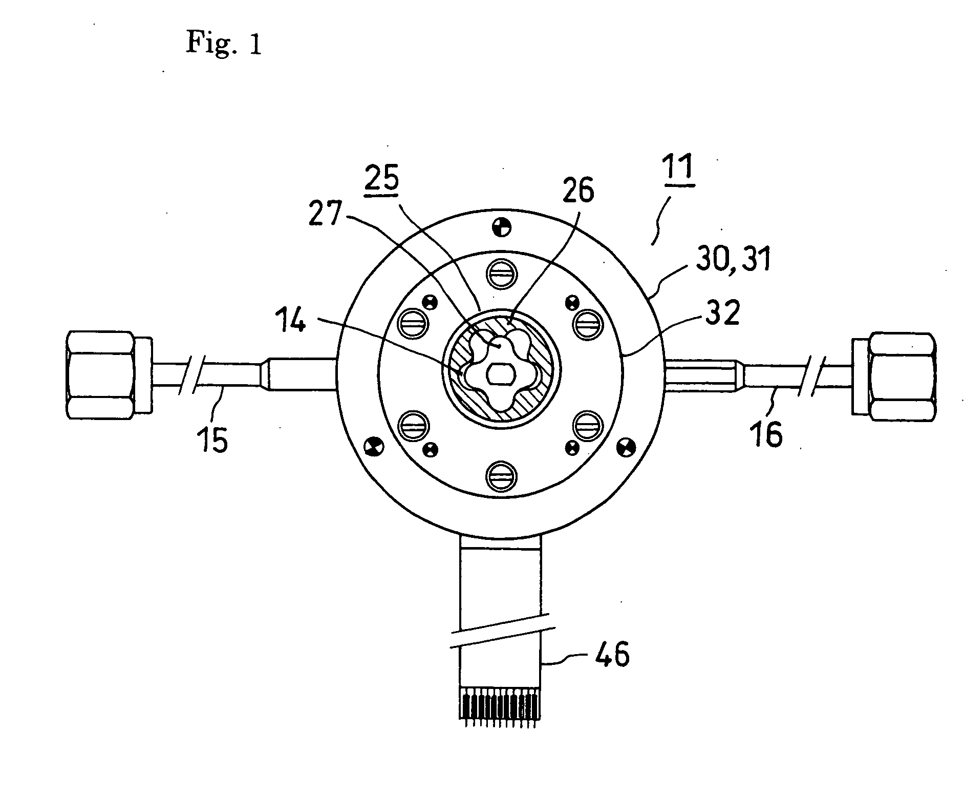
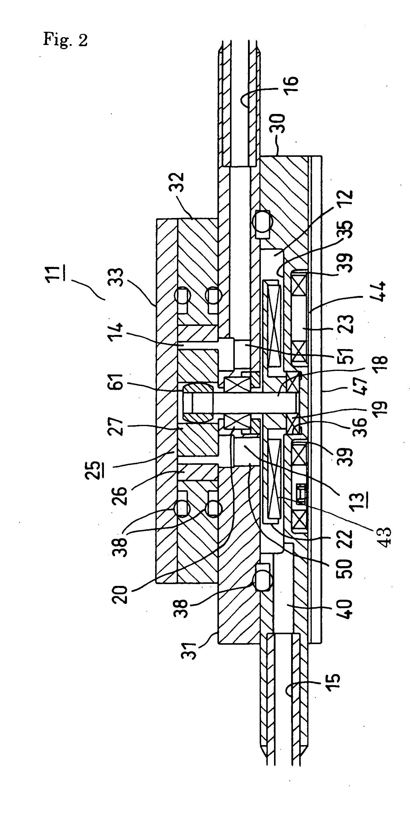
[0045]FIG. 1 is a plan view showing a whole configuration of a small size gear pump according to an embodiment of the present invention and FIG. 2 is a cross section showing main portion of the small size gear pump shown in FIG. 1 with an enlarged view. Here, FIG. 1 is a plan view in which an upper lid described later is removed.

[0046] As shown in the figures, a case 11 has nearly circular disc-shape configuration, in which a rotor chamber 12, a bearing chamber 13 and a gear chamber 14 are piled sequentially from the lower side of the case 11 to upward along the axial direction of the case 11. The rotor chamber 12 and the gear chamber 14 have a flat cylindrical shape respectively and they are communicating with each other through the bearing chamber 13, the detailed compositions of which will be explained later. The axial center of the gear c...


PUM

PropertyMeasurementUnit
Forceaaaaaaaaaa
Sizeaaaaaaaaaa
Magnetismaaaaaaaaaa

Abstract

A circular disc shape case 11 includes a motor rotor chamber 12, a bearing chamber 13 and a gear chamber 14 piled sequentially and being communicated with each other. A suction port 15 is connected to the motor rotor chamber 12, and a discharge port 16 is connected to the gear chamber 14, which communicate with outside respectively.
A rotating shaft 18 having an end positioned in the motor rotor chamber 13 and the other end extending to the gear chamber 14. A rotor 22 is fixed around the rotation shaft 18 in the motor rotor chamber 13.
A first bearing 19 is provided for supporting the end of the rotating shaft 18 in radial and thrust directions. A second bearing 20 is provided in the bearing chamber 13 for supporting an intermediate portion of the rotating shaft 18 in radial direction.
A trochoid gear 25 is provided in the gear chamber 14, having an outer rotor 26 and an inner rotor 27, which functions as a pump, taking in a fluid through the suction port pipe 15, and discharging the fluid from the discharge port 16.

Description

BACKGROUND OF THE INVENTION [0001] The present invention relates to a small size gear pump used for equipments and systems such as a cooling system used for electronic devices, medicine feeding system used in medical field such as artificial dialysis, medicine delivery system for chemical related equipments etc., which are required to have a small and a thin package size. [0002] Generally, in heat exchange system, water, alternative chlorofluorocarbon, alcohol kind, glycol kind, or ammonia are used as a heat medium. Pumps feeding such heat media are classified as a turbo type pump of an axial flow type or of a centrifugal type having a constant pressure and a volume type pump of a rotary type or of a reciprocating type having a constant volume. However, the conventional pumps have such draw backs as having a large size, having an insufficient suction efficiency or having high electric power consumption. [0003] Recent electronic devises generate an extremely lot of heat in accordance...

Claims


Application Information

Patent Timeline
IPC IPC(8): F04C2/08F04C2/10F04C15/00
CPCF04C2/084F04C2/102F04C15/008F05C2201/0406F05C2201/0409F05C2201/046F05C2253/20F05C2203/08F05C2203/0882F05C2225/04F05C2225/10F05C2225/12F05C2201/0466
Inventor MIYAGI, NAOKIYAMAMOTO, FUJIOMURAI, YUICHIMIYAZAKI, KOJIMATSUI, FUTOSHIAOYAGI, YUJI
Owner MIYAGI NAOKI
Why Eureka
Try Eureka