Window Fan

a technology for windows and fans, applied in lighting and heating apparatus, ventilation systems, heating types, etc., can solve the problems of poor circulation within the room, affecting cooling, and unable to eliminate temperature stratification, so as to improve cooling and increase circulation

Inactive Publication Date: 2011-02-17
WIESE JAMES
View PDF90 Cites 20 Cited by
  • Summary
  • Abstract
  • Description
  • Claims
  • Application Information

AI Technical Summary

Benefits of technology

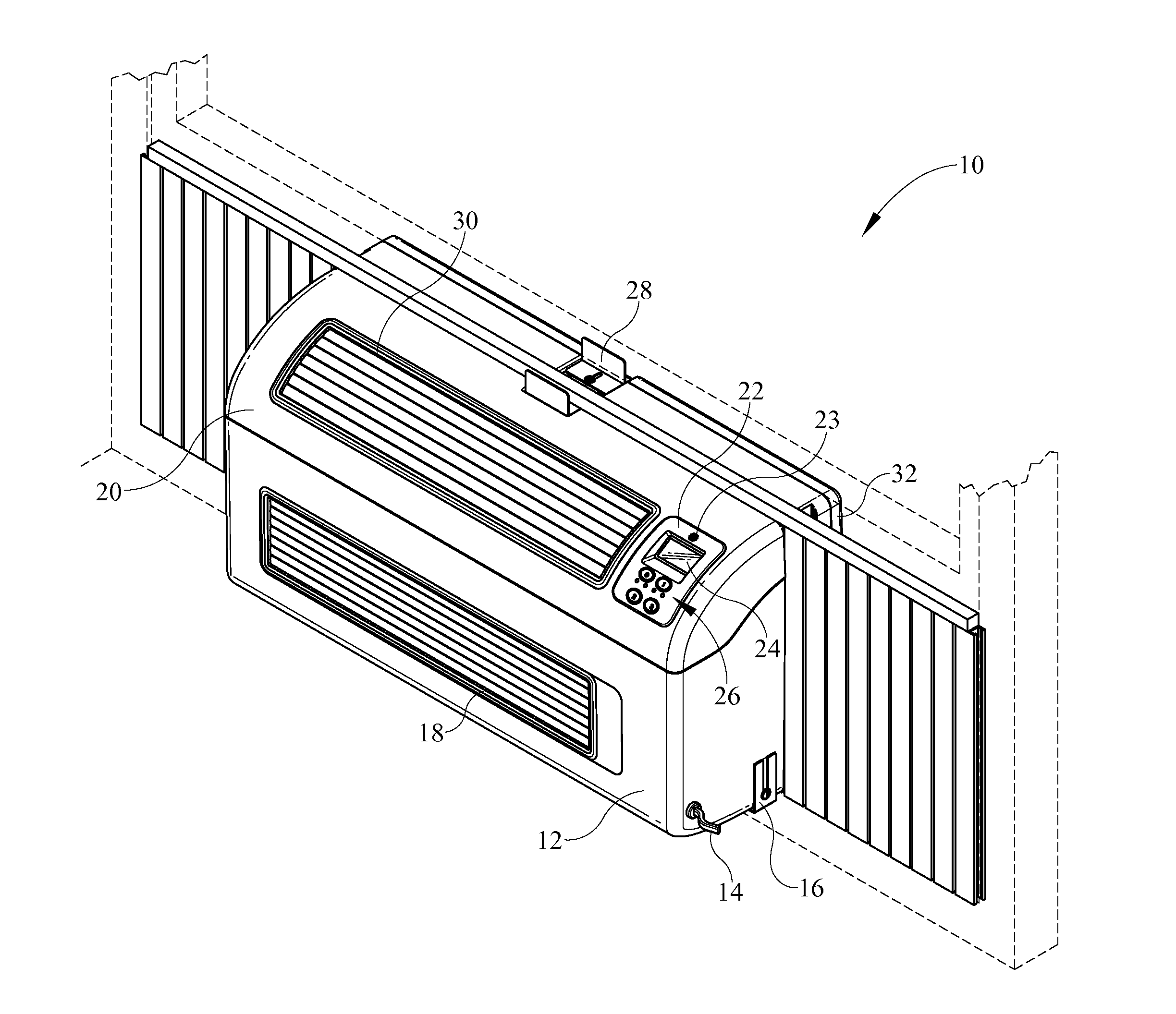
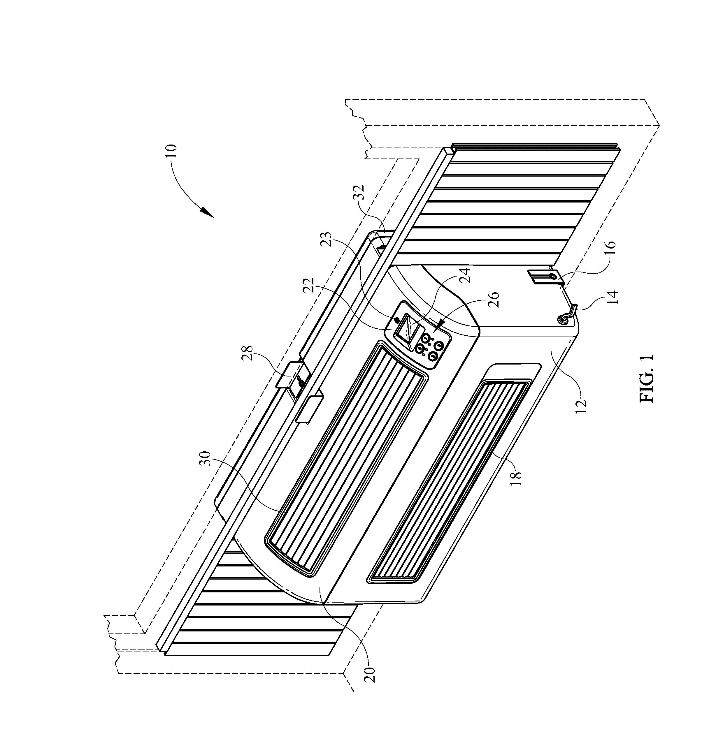
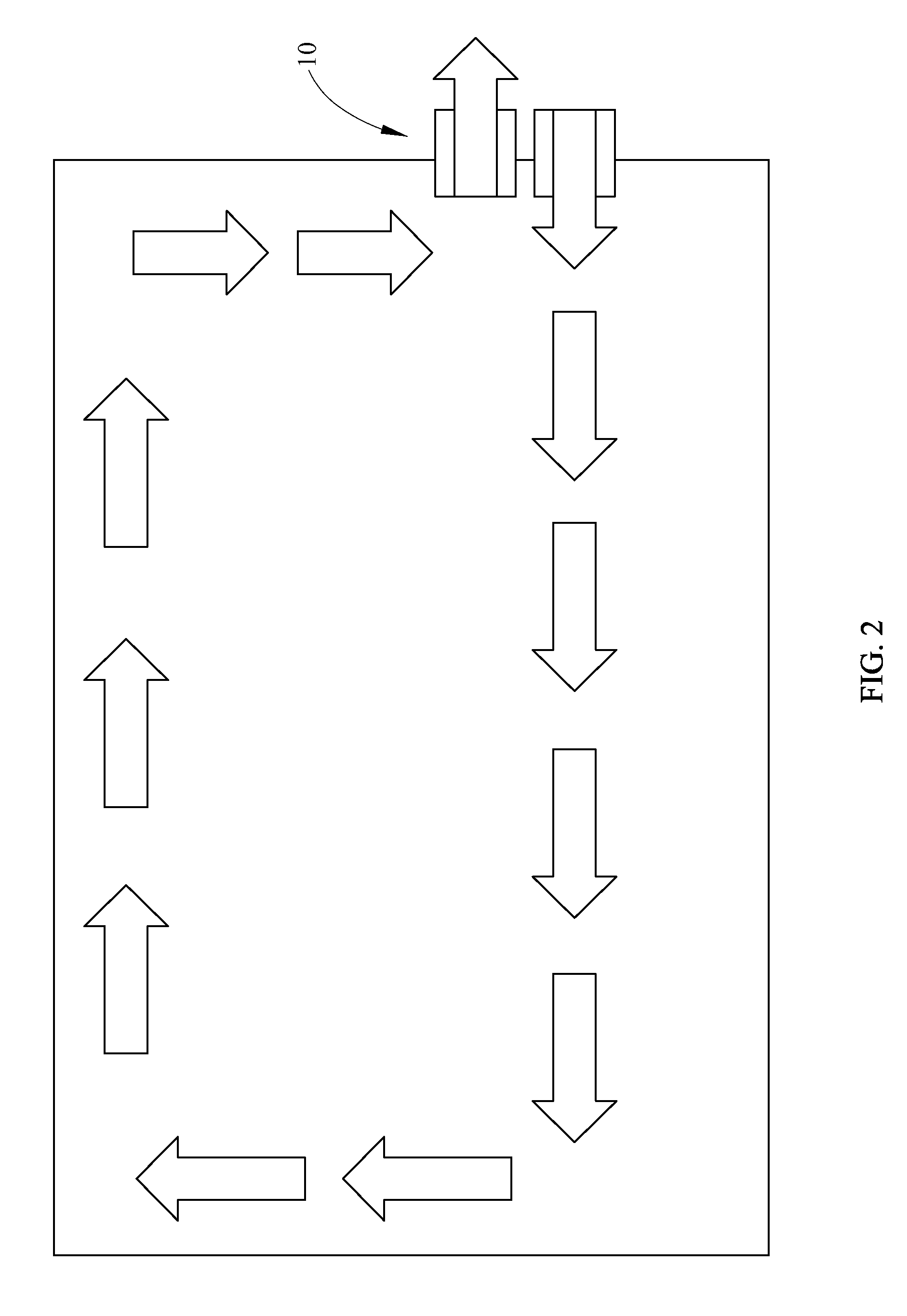
[0014]In some embodiments a window fan comprises a housing having an air intake and an air exhaust output both in the housing and on an exterior side of a building. The window fan also comprises an air output on an interior side of the building, the air output being in fluid communication with the air intake through a duct in the housing. The air exhaust is in fluid communication with an exhaust intake on a building interior side of the housing. A first fan is disposed vertically above a second fan within the housing. One of the first fan and the second fan is in flow communication with the air intake and the air output, the other of the first fan and the second fan is in flow communication with the air exhaust and the exhaust intake. The first fan and the second fan may draw warmer air from the interior side of the building and cooler air from the exterior side of the building. The first fan and the second fan may remove warm air from in the building and increase circulation for improved cooling. The window fan may further comprise a partition separating a first airflow path from a second airflow path. The window fan may further comprise a first partition separating a first airflow path from a second airflow path. The window fan may further comprise the first airflow path and the second airflow path moving in opposite directions through the housing. The window fan may further comprise a movable louver system for positioning on a building interior side of the housing. The window fan may further comprise at least one actuating motor connected to a linkage for opening and closing louvers.

Problems solved by technology

There are various known problems however, with prior art fan structures.
First, as depicted in FIG. 15, prior art fans in many cases only pull air into a room and fail to exhaust air which causes poor circulation within the room and therefore hinders cooling.
Therefore these fan systems fail to eliminate temperature stratification and reduce cooling effectiveness.
Another problem related to prior art fans is that fan units do no inhibit water passing through a housing and into a room when the fan is operated while a rain event is occurring.
Consequently, during rain events, many window fans may not be operated without drawing water into the building.
Another problem with prior art window units is the limited control of fan operation.

Method used


Image

  • Window Fan
  • Window Fan
  • Window Fan

Examples


Embodiment Construction

[0037]It is to be understood that the invention is not limited in its application to the details of construction and the arrangement of components set forth in the following description or illustrated in the drawings. The invention is capable of other embodiments and of being practiced or of being carried out in various ways. Also, it is to be understood that the phraseology and terminology used herein is for the purpose of description and should not be regarded as limiting. The use of “including,”“comprising,” or “having” and variations thereof herein is meant to encompass the items listed thereafter and equivalents thereof as well as additional items. Unless limited otherwise, the terms “connected,”“coupled,” and “mounted,” and variations thereof herein are used broadly and encompass direct and indirect connections, couplings, and mountings. In addition, the terms “connected” and “coupled” and variations thereof are not restricted to physical or mechanical connections or couplings...


PUM


Abstract

In the specification and drawings a window fan is described and shown. The window fan cools a room using outside air when the room air meets certain criteria relative to a set point and the outside air meets certain preselected criteria relative to the indoor air. The window fan may also exhaust room air to the outside when the room air meets certain criteria relative to a set point and the outside air meets certain preselected criteria relative to the indoor air

Description

CROSS REFERENCES TO RELATED APPLICATIONS[0001]None.STATEMENT REGARDING FEDERALLY SPONSORED RESEARCH OR DEVELOPMENT[0002]None.REFERENCE TO SEQUENTIAL LISTING, ETC.[0003]None.BACKGROUND[0004]1. Field of the Invention[0005]This invention relates to a seasonally installed window fan. More specifically, the invention relates to a seasonally installed window fan which cools a room using outside air when the room air meets certain criteria relative to a set point and the outside air meets certain preselected criteria relative to the indoor air.[0006]2. Description of the Related Art[0007]Prior art window fans are utilized to move stagnant air, cool internal building areas or rooms when air conditioning is not available. There are various known problems however, with prior art fan structures. First, as depicted in FIG. 15, prior art fans in many cases only pull air into a room and fail to exhaust air which causes poor circulation within the room and therefore hinders cooling. Alternatively,...

Claims


Application Information

Patent Timeline
Patent Type & Authority Applications(United States)
IPC IPC(8): F24F7/013
CPCF24F7/013F24F2011/0016F24F11/0015F24F11/0001F24F2110/10F24F2110/20F24F2110/22F24F11/30F24F11/77F24F11/46F24F11/523F24F11/63F24F11/86
Inventor WIESE, JAMES
Owner WIESE JAMES
Why Eureka
Try Eureka