
Advanced valve metal anodes with complex interior and surface features and methods for processing same

a metal anode, advanced technology, applied in the direction of electrochemical capacitors, liquid electrolytic capacitors, electrochemical capacitors, etc., can solve the problems of compromising the performance of the completed electrochemical cell, the battery(s) and high voltage capacitor(s) used to provide effective cardioversion/defibrillation therapy, and the energy required for effective cardioversion/defibrillation therapy have historically been relatively bulky and expensive, and achieves small size and shape flexibility of powdered

Inactive Publication Date: 2008-03-11
MEDTRONIC INC
View PDF26 Cites 50 Cited by
  • Summary
  • Abstract
  • Description
  • Claims
  • Application Information

AI Technical Summary

Benefits of technology

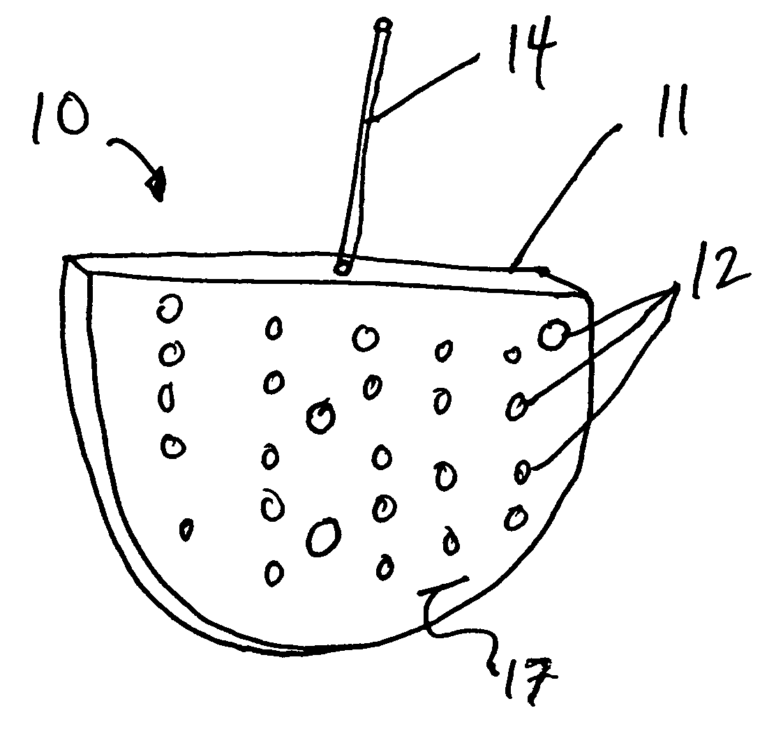
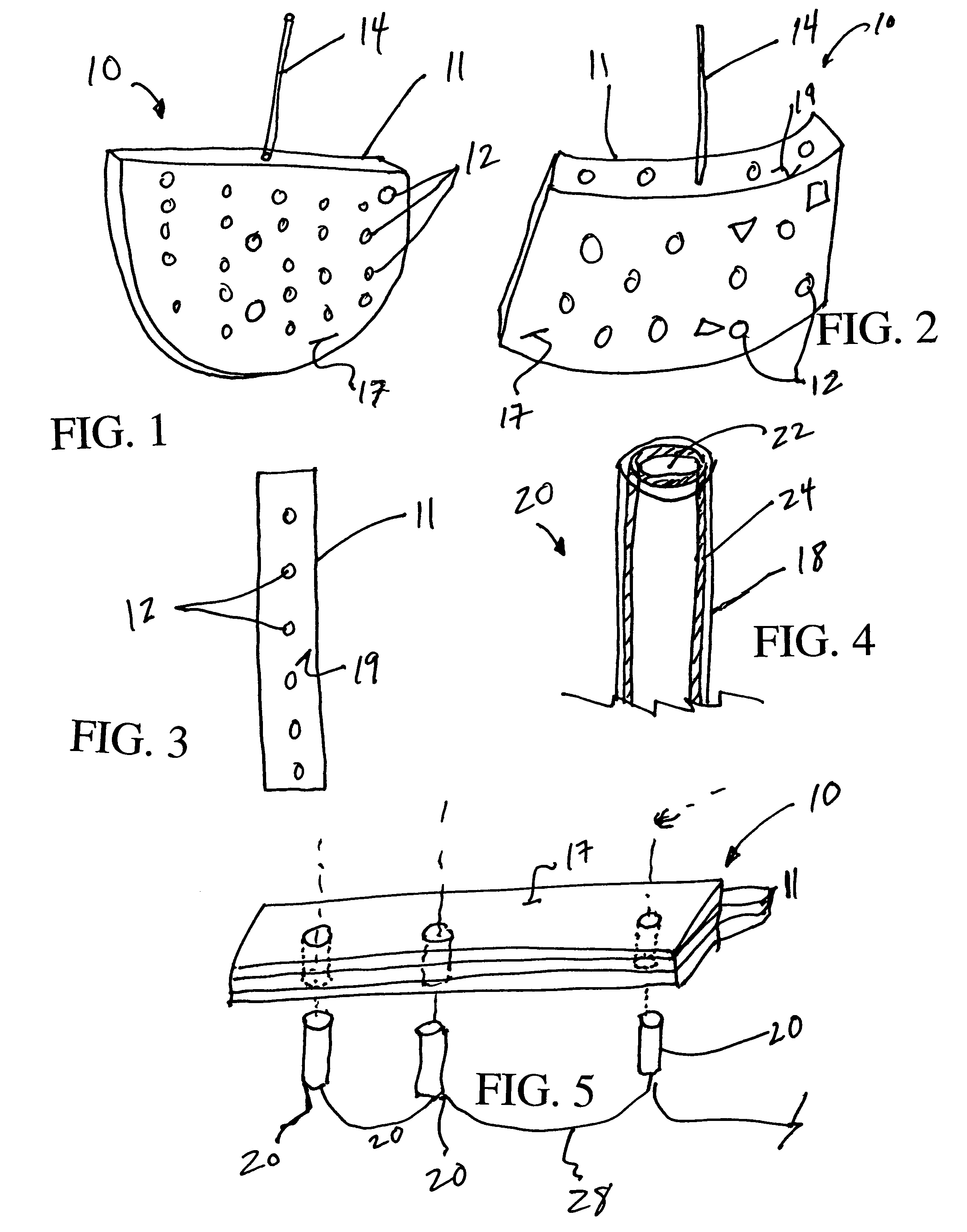
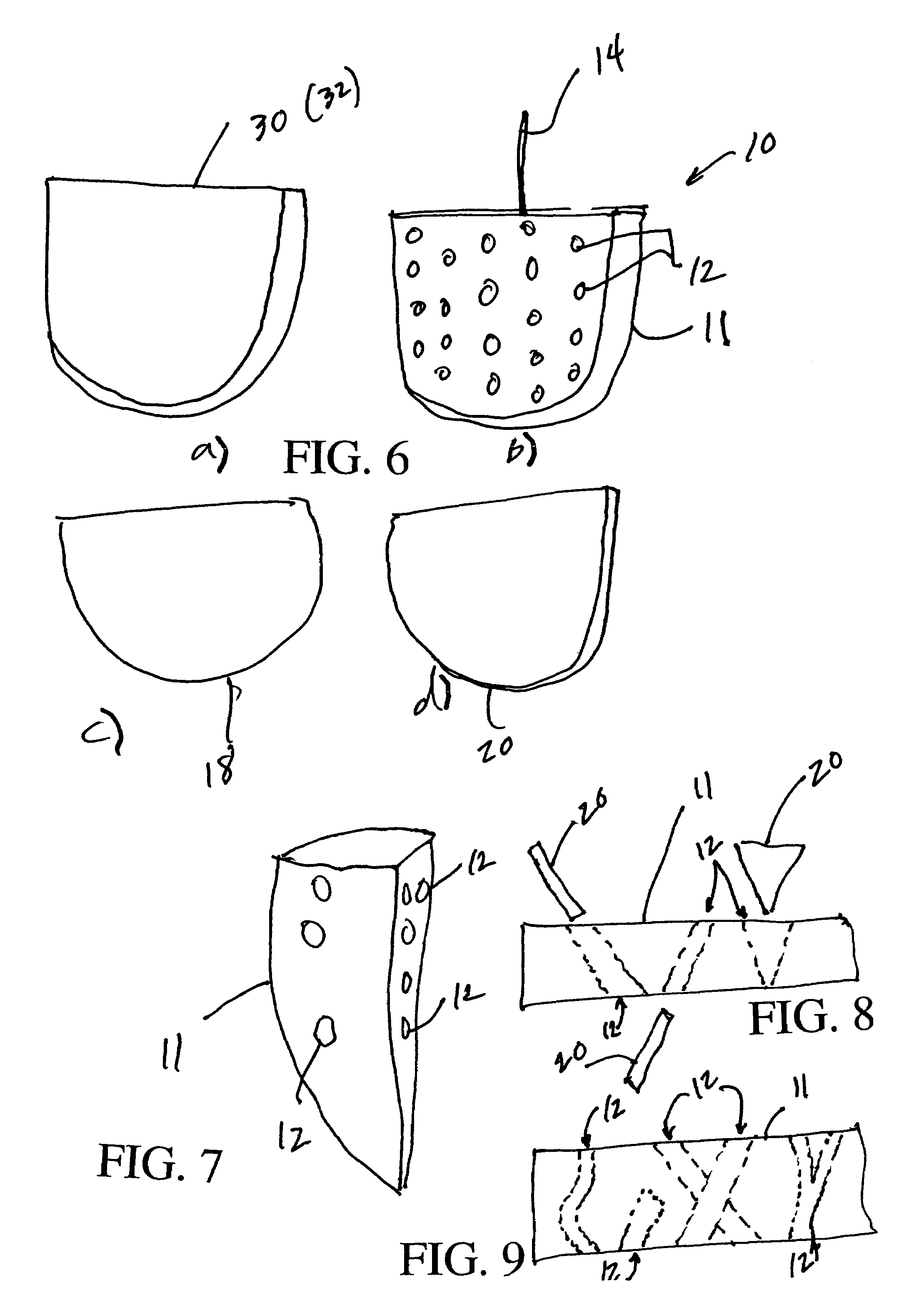
[0009]The present invention provides improved capacitor fabrication techniques and devices wherein pre-processing of valve metal anodes provides diverse complex anode shapes and promotes free circulation of liquid electrolyte in, through and about the anode. Such pre-processing includes shaping an anode and providing surface and interior features (e.g., through-holes, ports, bores, tunnels, channels, irregular surface features and the like) to provide what are referred to herein as advanced valve metal (AVM) anodes. Pre-processing of AVM anodes prior to formation of oxide on the exterior and exposed interior surfaces of a pressed and sintered anode provides for robust, compact AVM capacitors for IMDs. The inventors recognized that forming valve metal anodes to high voltages, greater than about 200 V, frequently results in structural failure of the anode and that uniquely shaped anodes according to the present invention provide superior high voltage anode electrodes.
[0010]One significant aspect of the present invention includes enhanced circulation of liquid electrolyte—both formation electrolyte and working electrolyte. Due to enhanced electrolyte circulation (including electrolyte replenishment during formation) the active energy density of the capacitor may be increased (e.g., by altering anode porosity). The present invention offers advantages, particularly as compared with prior art capacitors and methods for fabricating, forming and operating capacitors in conjunction with IMDs such as ICDs as well as other medical devices that may frequently charge and therapeutically discharge one or more high voltage capacitors, as may be employed in clinics and hospitals. The AVM anodes of the present invention can be designed to optimize package efficiency of an IMD. According to the present invention perforated and non-perforated AVM anodes, with complex and irregular geometric shapes, may be efficiently provided that enhance the overall packaging efficiency of compact IMDs, such as ICDs. Such AVM anodes may be shaped to accommodate one or more elongated cathode members wherein the surface or interior features of the AVM anode correspond to the shape of the cathode member(s).
[0012]The inventors also discovered that for both sintered- and etched foil-type anodes, the porous electrode structure restricts movement of ions within the electrolyte necessary to complete the electrical circuit between anode and cathode. As a result, the equivalent series resistance (ESR) of the capacitor increases if the anode thickness is increased in an attempt to increase the active energy density of the capacitor. The introduction of an array of through-holes in the face or side surfaces of the anode slug (or etched foil stack) improves ESR (i.e., decreases ESR).
[0014]The present invention takes advantage of the small size and shape flexibility of powdered metal anodes so that highly compact and ergonomic IMDs can be produced. In comparison to aluminum plate, flat electrolytic capacitors (FECs) having hundreds of discrete parts and components and require attendant complex manufacturing procedures, AVM anodes have few parts and relatively simple manufacturing procedures. Beginning with relatively pure powdered metal (often including a binder), a manufacturing process for AVM anodes according to the present invention involves pressing the powder to a given press-density and into a desired shape, washing the pressed anode, sintering the anode (at approximately 1300-1450 degrees Celsius in a reduced pressure atmosphere), washing the anode, annealing the anode (at 350 degrees Celsius in ambient air), and reforming the anode (to cure any oxide deformation from the annealing step).
[0015]A wide variety of perforated and porous AVM anodes according to certain embodiments of the present invention provide: (i) improved thermal characteristics (during anode formation), (ii) reduced ESR (especially important during operation of an AVM anode in an IMD), (iii) integrated, interlocking anode-cathode elements (high capacitance, insulated cathode rods inserted into at least some of said perforations), and (iv) increased and enhanced manufacturability due to ease of alignment of anode and cathode members during fabrication of capacitors built according to the present invention.

Problems solved by technology

This overheating adversely affects oxide formation and may cause electrolyte residue to accumulate, further compromising performance of the completed electrochemical cell.
The battery(s) and high voltage capacitor(s) used to provide and accumulate the energy required for the effective cardioversion / defibrillation therapy have historically been relatively bulky and expensive.

Method used


Image

  • Advanced valve metal anodes with complex interior and surface features and methods for processing same
  • Advanced valve metal anodes with complex interior and surface features and methods for processing same
  • Advanced valve metal anodes with complex interior and surface features and methods for processing same

Examples


example 1

[0063]A method of fabricating a valve metal anode, comprising the steps of:[0064]depositing a metallic powder in a receiving container;[0065]applying pressure to the metallic powder to form a raw anode at a first press-density;[0066]removing the raw anode from the container;[0067]removing portions of the raw anode;[0068]sintering the raw anode;[0069]depositing the raw anode in an electrolyte solution; and[0070]applying electrical potential to the raw anode until an oxidation layer forms to a desired thickness on exposed portions of the raw anode.

example 2

[0071]A method according to example 1, wherein the depositing step b) further comprises:[0072]b1) depositing a first layer of the metallic powder having a first density characteristic;[0073]b2) depositing a second layer of the metallic powder having a second density characteristic which is different from said first density characteristic, on top of said first layer of metallic powder.

example 3

[0074]A capacitor apparatus, comprising:[0075]a porous sintered valve metal anode member having at least two cavities formed therein and having a layer of oxide formed on exposed surfaces of the anode member and wherein said valve metal anode has a cross-sectional density profile wherein a peripheral portion of the valve metal anode is less dense than a central portion of the valve metal anode;[0076]a conductive lead wire coupled to the anode member;[0077]at least one cathode member disposed in electrical communication with said anode member; and[0078]a housing means for retaining the anode member and cathode member.


PUM


Abstract

The present invention generally relates to improved capacitors; in particular, the present invention provides advanced valve metal (AVM) anodes and methods for fabricating AVM anodes having complex surface and interior features for use in high energy density capacitors. Such anodes find use in high voltage capacitors incorporated into implantable medical devices (IMDs), among other uses. The AVM anodes may be pressed into virtually any arbitrary shape and may have a gradually changing (or substantially constant) density profile throughout the AVM anode. Such AVM anodes may also be perforated or shaped to receive one or more cathode members. The AVM anodes enhance packaging efficiency for compact high energy density capacitors.

Description

CROSS REFERENCE TO RELATED APPLICATION[0001]The present non-provisional patent application claims the benefit of provisional patent application Ser. No. 60 / 429,304 filed 25 Nov. 2002 and entitled, “ELECTROLYTIC VALVE METAL ANODES INCORPORATING A TUNNEL OR CHANNEL ARRAY,” the contents of which are hereby incorporated by reference herein.FIELD OF THE INVENTION[0002]The present invention generally relates to improved capacitors; in particular, the present invention provides advanced valve metal (AVM) anodes and methods for fabricating AVM anodes having complex surface and interior features for use in high energy density capacitors. More particularly, such anodes find use in high voltage capacitors incorporated into implantable medical devices (IMDs), among other uses.BACKGROUND OF THE INVENTION[0003]The term “valve metal” represents a group of metals including aluminum, tantalum, niobium, titanium, zirconium, etc., all of which form adherent, electrically insulating metal-oxide films u...

Claims


Application Information

Patent Timeline
IPC IPC(8): H01G9/04A61N1/39H01B13/00H01G9/042H01G9/048H01G9/052H01G9/06H01G9/08
CPCH01G9/042H01G9/052H01G9/06H01G9/08A61N1/3956
Inventor HOSSICK-SCHOTT, JOACHIMNORTON, JOHN D.RORVICK, ANTHONY W.MAY, STEVE J.
Owner MEDTRONIC INC
Learn More