
Vehicle seat

a technology for vehicles and seats, applied in the field of vehicles seats, can solve the problems of increasing the size of the entire configuration, and achieve the effect of increasing the size and complexity of the configuration of both links

Active Publication Date: 2011-02-24
TOYOTA BOSHOKU KK +2
View PDF12 Cites 10 Cited by
  • Summary
  • Abstract
  • Description
  • Claims
  • Application Information

AI Technical Summary

Benefits of technology

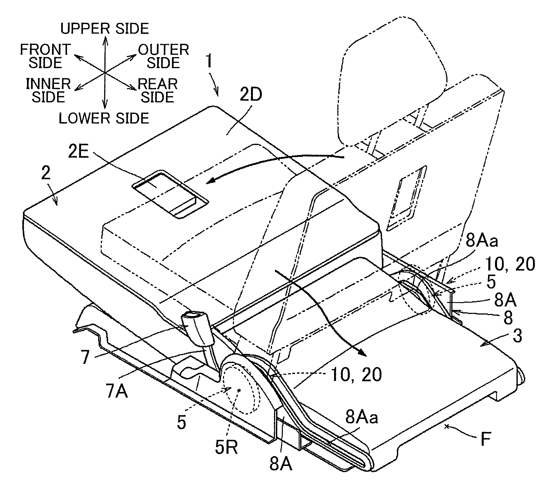
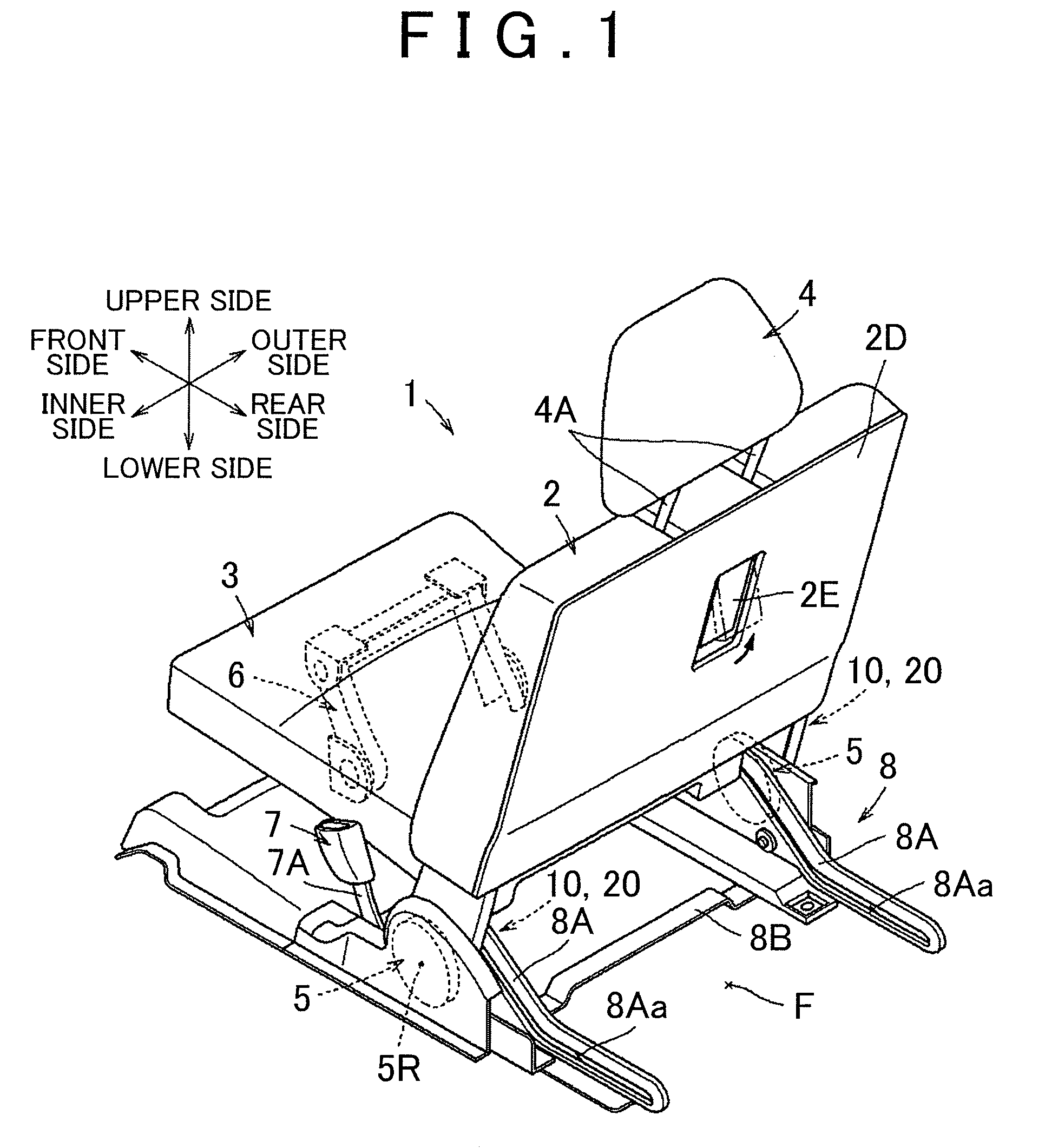
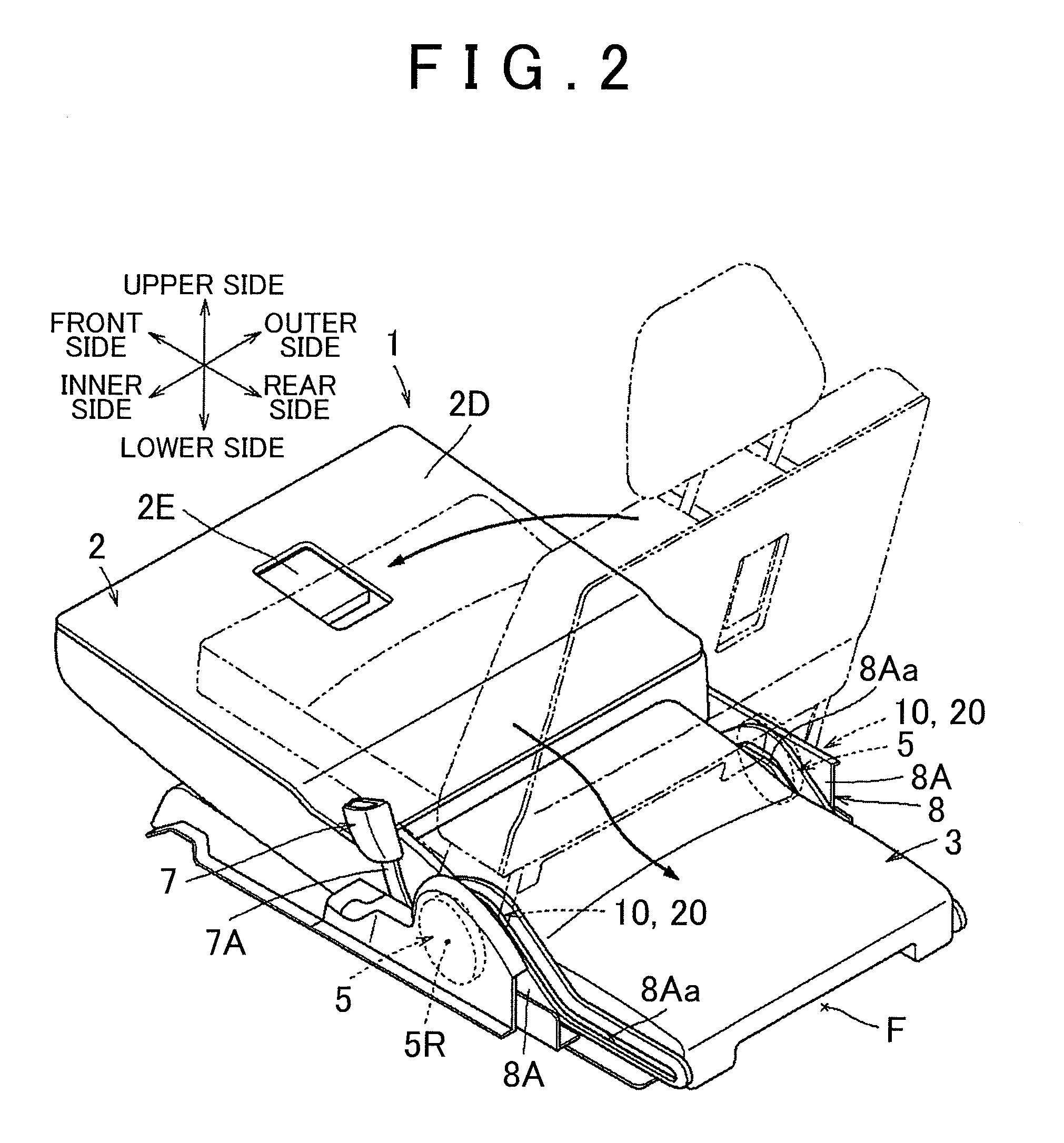
[0010]With the first aspect, the first link operated by the operating member is provided for the seat back, so the rotational position (direction) of the first link with respect to the second link is changed as the seat back is tilted forward. Here, when the seat back is tilted forward, the first link is moved together with the seat back in a direction to be separated from the second link, that is, in a direction opposite to a direction in which the first link turns the second link. Therefore, when the seat back is tilted forward, it is not configured so that the first link is rotated in a direction to further turn the second link and then the arrangement of both links is inverted, but it is configured so that the first link moves in a direction to be separated from the second link. Therefore, it is possible to obtain the configuration with no inverted arrangement of both links without an increase in size and complexity of the configuration of both links.

Problems solved by technology

However, according to the above existing art, one of the first and second links needs to have a relief structure, so there is a problem that the size of the entire configuration increases.

Method used


Image

  • Vehicle seat
  • Vehicle seat
  • Vehicle seat

Examples


Embodiment Construction

[0026]Hereinafter, an embodiment of the invention will be described with reference to the accompanying drawings.

[0027]The configuration of a vehicle seat 1 according to a first embodiment will be described with reference to FIG. 1 through FIG. 10. Here, FIG. 1 shows the configuration of the vehicle seat 1 according to the present embodiment. The vehicle seat 1 may be provided in the rearmost row in a vehicle equipped with three seat rows. The vehicle seat 1 includes a seat back 2, a seat cushion 3 and a headrest 4. The seat back 2 serves as a backrest for a seated occupant. The seat cushion 3 serves as a seating portion. The headrest 4 supports the head of a seated occupant.

[0028]More specifically, the vehicle seat 1 may be one of two seats provided in the third seat row, and is arranged at the right side when viewed from the rear side of the vehicle. Then, a side rim that constitutes a vehicle body side wall (not shown) is attached next to an outer side portion of the seat on the r...


PUM


Abstract

A vehicle seat includes an operating member that is provided for a seat back. The operating member is operated to release locking of a seat cushion to a floor and to release rotation-sopped state of a reclining device. By operating the operating member, a first link rotatably provided for the seat back is operated in one rotation direction to thereby turn a second link rotatably provided for a base frame so that locking of the seat cushion to the floor is released. When the seat back is tilted forward, the first link is moved together with the seat back in a direction to be separated from the second link, that is, in a direction opposite to a direction in which the first link turns the second link.

Description

INCORPORATION BY REFERENCE[0001]The disclosure of Japanese Patent Application No. 2009-192066 filed on Aug. 21, 2009 including the specification, drawings and abstract is incorporated herein by reference in its entirety.BACKGROUND OF THE INVENTION[0002]1. Field of the Invention[0003]The invention relates to a vehicle seat. More specifically, the invention relates to a vehicle seat that is configured so that an operating member is operated to release locking of a seat cushion to a floor.[0004]2. Description of the Related Art[0005]In an existing vehicle seat, there is known a mechanism that releases locking of a seat cushion to a floor by tilting a seat back forward to thereby allow the seat cushion to be shifted into a retracted position. Here, Japanese Patent Application Publication No. 2002-67761 (JP-A-2002-67761) describes a mechanism in which a seat back is tilted forward to cause a first link that rotates together with the seat back to turn a second link that releases the locki...

Claims


Application Information

Patent Timeline
Patent Type & Authority Applications(United States)
IPC IPC(8): B60N2/20
CPCB60N2/3013B60N2002/363B60N2/3065
Inventor NAKANE, RYOSHUWADA, TOSHINAOIWASA, KAZUYA
Owner TOYOTA BOSHOKU KK
Learn More