Radio communication system

Inactive Publication Date: 2011-02-24
NTT DOCOMO INC
View PDF17 Cites 56 Cited by
  • Summary
  • Abstract
  • Description
  • Claims
  • Application Information

AI Technical Summary

Problems solved by technology

Therefore, the mobile station UE located in a shadow region 3 is unable to ensure a line-of-sight path from the radio base station BS, and thu

Method used


Image

  • Radio communication system
  • Radio communication system
  • Radio communication system

Examples


first embodiment

Radio Communication System of the Present Invention

[0044]A radio communication system according to a first embodiment of the present invention will be described with reference to FIG. 3 to FIG. 5.

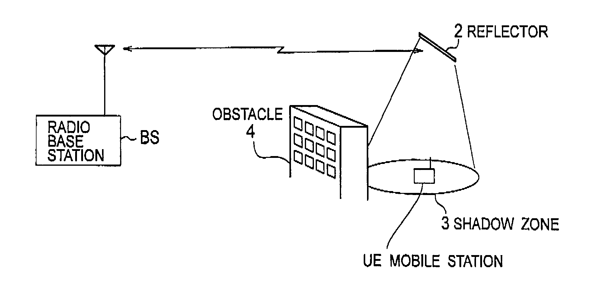
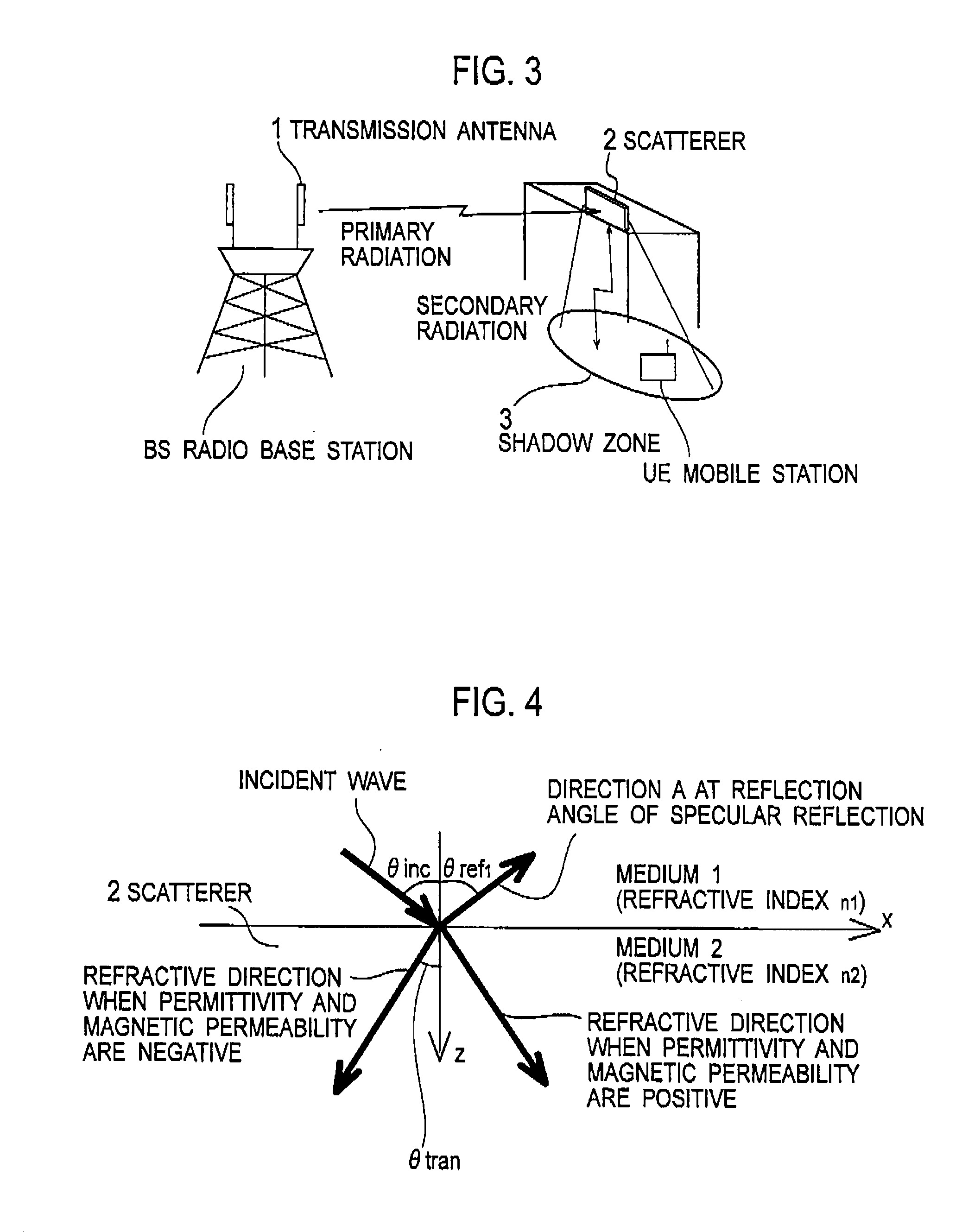
[0045]As shown in FIG. 3, the radio communication system according to the present embodiment includes a scatterer 2 configured to reflect, refract, or transmit a radio wave that is radiated primarily from a radio base station BS (transmission side apparatus) so that the radio wave is radiated secondarily to a mobile station (a receiving side apparatus) located in a shadow region 3 (a desired area).

[0046]Here, in the present embodiment, the transmission side apparatus may be a mobile station while the receiving side apparatus may be the radio base station BS.

[0047]In the present embodiment, a metamaterial is used as the scatterer 2. In the present embodiment, the “metamaterial” is a material which is formed by arranging a predetermined structure, and which artificially determines surface im...

modified examples

[0124]It is to be noted that the above-described scatterer 2 may have a structure in which the surface on which the radio wave is made incident is not parallel to the surface from which the radio wave is secondarily radiated, or may be configured by a frequency selective surface having the FSS structure.

[0125]Meanwhile, the above-described scatterer 2 may employ as the metamaterial a material (an artificial dielectric body or an artificial magnetic body), of which at least one of the permittivity ∈ and the magnetic permeability μ is negative.

[0126]Here, the artificial dielectric body having the negative permittivity ∈ can be implemented by an array of rods having the periodic structure. Meanwhile, the artificial magnetic body having the negative magnetic permeability μ can be implemented by a resonant ring having the periodic structure.

[0127]Further, a material (a left-handed material) having the permittivity ∈ and the magnetic permeability μ which are both negative may be implement...


PUM


Abstract

A radio communication system according to the present invention includes a scatterer configured to reflect, refract, or transmit a radio wave radiated primarily from a transmission side apparatus to radiate the radio wave secondarily to a desired area and a metamaterial is used for the scatterer.

Description

TECHNICAL FIELD[0001]The present invention relates to a radio communication system including a scatterer which is configured to reflect, refract, or transmit a radio wave radiated primarily from a transmission side apparatus and to thereby radiate the radio wave secondarily to a desired area.BACKGROUND ART[0002]As shown in FIG. 1, a method using a reflector 2 in a radio communication system is proposed in order to improve communication quality between a radio base station BS and a mobile station UE. The reflector 2 is configured to reflect a radio wave radiated primarily from the radio base station BS (a transmission side apparatus) so that the radio wave is reflected secondarily.[0003]To be more specific, as shown in FIG. 1, the radio wave radiated primarily from the radio base station BS is blocked by an obstacle 4 such as a building. Therefore, the mobile station UE located in a shadow region 3 is unable to ensure a line-of-sight path from the radio base station BS, and thus is u...

Claims


Application Information

Patent Timeline
IPC IPC(8): H04W40/34
CPCH01Q3/46H01Q15/02H01Q15/08H01Q15/0086H04B7/145H04W16/26H01Q15/14
Inventor MARUYAMA, TAMAMIUEBAYASHI, SHINJIFURUNO, TATSUO
Owner NTT DOCOMO INC
Why Eureka
Try Eureka