Switch valve

Active Publication Date: 2011-03-03
ULVAC INC
View PDF8 Cites 1 Cited by
  • Summary
  • Abstract
  • Description
  • Claims
  • Application Information

AI Technical Summary

Benefits of technology

[0024]Since the lower end of the blocking member closely contacts the melted metal without a gap, the gas blocking performance is higher than that in a case where it contacts a solid. Furthermore, even when the switch valve is repeatedly opened and closed, the lower end of the blocking member is not abraded, so that the switch valve has a long span of life. Moreo

Problems solved by technology

, sealing faces are damaged, so that the se

Method used


Image

  • Switch valve
  • Switch valve
  • Switch valve

Examples


first embodiment

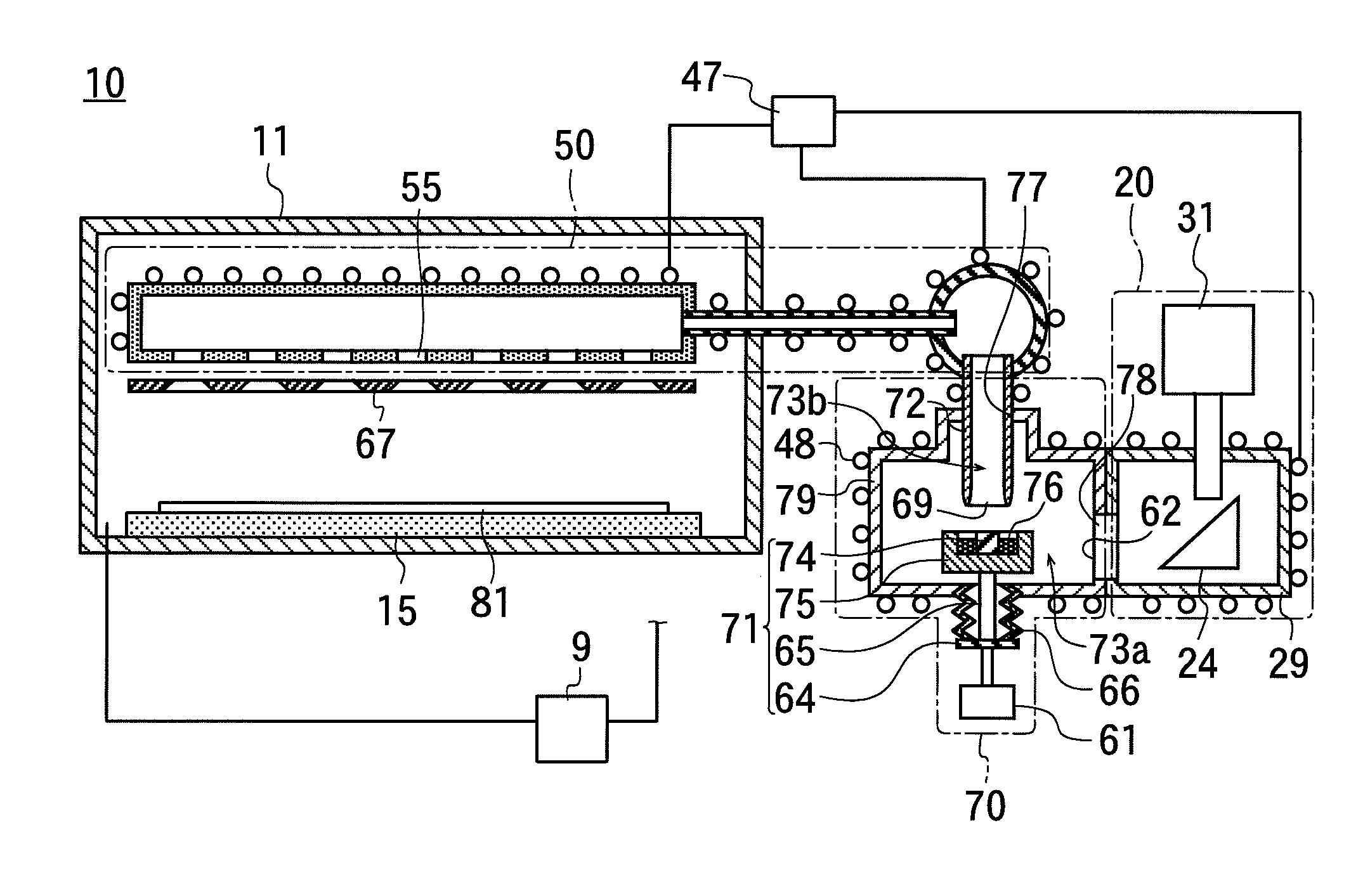
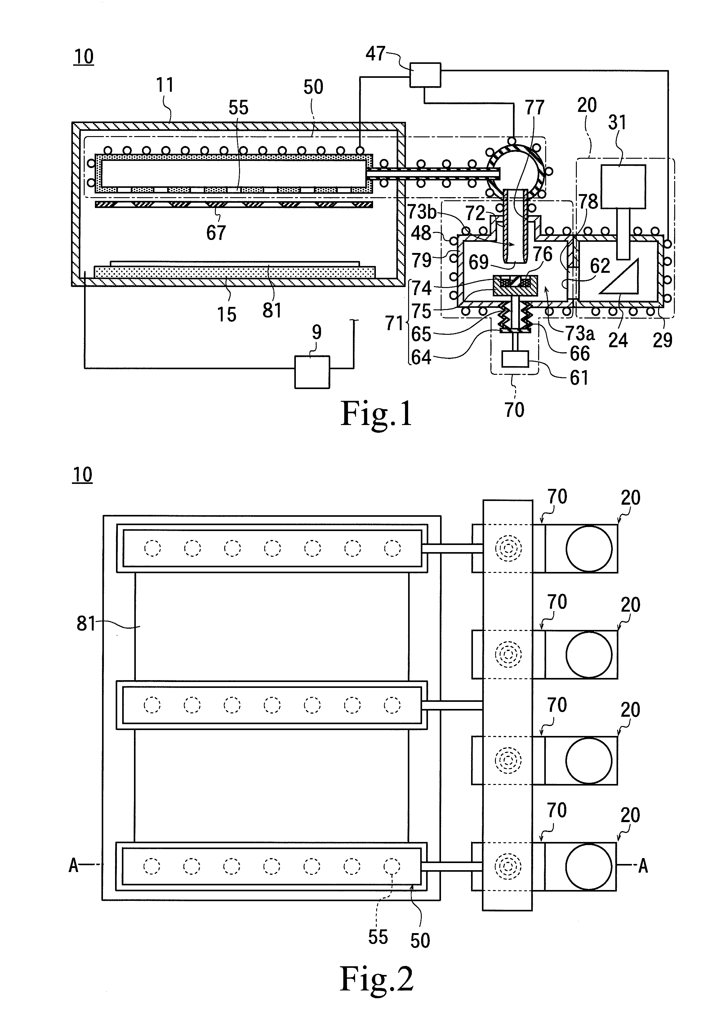
[0042]In FIG. 2, a reference numeral 10 is one example of a film forming apparatus with the switch valve 70 used in the present invention. FIG. 1 corresponds to a sectional view of FIG. 2 cut along an A-A section line.

[0043]The switch valve 70 has a low-melting-point metal 76, a receiving member 71, an enclosure 79, a blocking member 72, and an extensible member 66. The enclosure 79 is arranged such that at least part of it is located above an opening of the receiving member 71.

[0044]In this embodiment, the enclosure 79 is in a box shape, with an opening formed at a bottom face. A receiving member 71 has a supporting plate 64 which is arranged under the enclosure 79, a supporting shaft 65 which is set upright on a surface of the supporting plate 64 and has a tip projected into the enclosure 79 through an opening at a bottom face of the enclosure 79, and a vessel 75 attached to the tip of the supporting shaft 65. An opening of the vessel 75 is directed upwardly, and a low-melting poi...

second embodiment

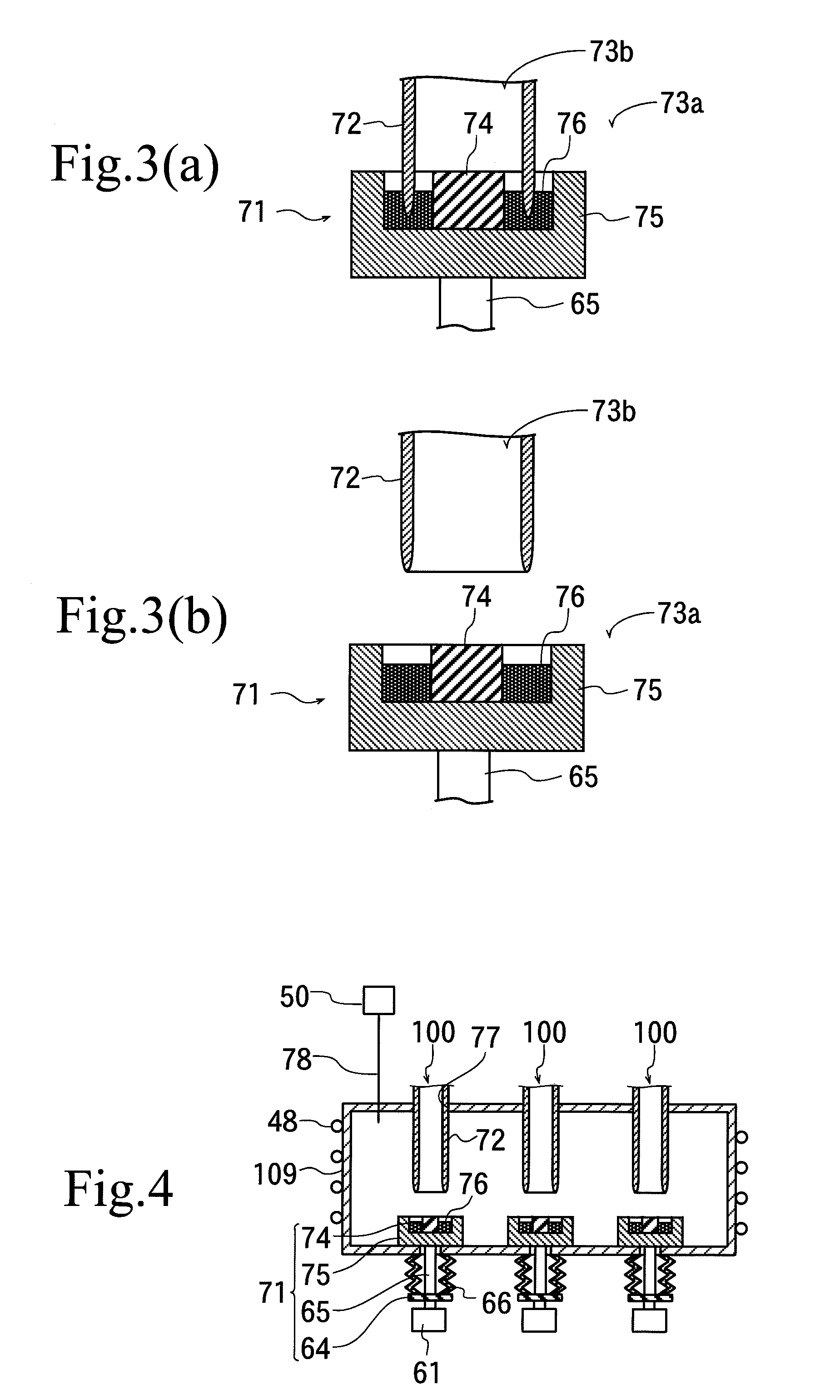
[0077]Next, the switch valve 100 of the present invention will be explained (FIG. 4).

[0078]The switch valve 100 of the second embodiment has the same structure as in the switch valve 70 of the above-discussed first embodiment except that a plurality of the switch valves 100 share an enclosure 109, and an explanation will be made with the same reference numerals that have been given to the same members.

[0079]In the switch valve 100 of the second embodiment, the enclosure 109 is fixed, and receiving members 71 are designed to move.

[0080]The enclosure 109 is in a shape of a box, and its bottom face is provided with openings in such a number that is equal to the number of the receiving members 71. The receiving member 71 has a supporting plate 64 arranged under the enclosure 109, a supporting shaft 65 set upright on a surface of the supporting plate 64 and with its tip projected inside the enclosure 109 through the opening at the bottom face of the enclosure 109, and a vessel 75 attache...


PUM


Abstract

A switch valve having a long span of life is provided. The switch valve 70 of the present invention has a low-melting-point metal 76 having a surface on which a blocking member contacts, with the low-melting-point metal 76 melted, thereby a closed state appears in which an inner space of the switch valve 70 is split up into an inner space and an outer space of the blocking member 72. When the inner space and the outer space of the blocking member 72 are connected in the inner space of the switch valve 70, outside devices are blocked from each other in the closed state. The outside devices are connected to each other in an opened state in which the lower end of the blocking member 72 is spaced away from the low-melting-point metal 76.

Description

[0001]This application is a continuation of International Application No. PCT / JP2009 / 053580 filed Feb. 26, 2009, which claims priority to Japanese Patent Document No. 2008-044350, filed on Feb. 26, 2008. The entire disclosure of the prior application is herein incorporated by reference in their entireties.BACKGROUND OF THE INVENTION[0002]1. Field of the Invention[0003]The present invention relates to a switch valve; and in particular, the invention relates to a switch valve to be used for switching between start and stop in feeding a gas.[0004]2. Description of Background Art[0005]The switch valves have been conventionally used in switching between the feeding start and the feeding stop of gases.[0006]In FIGS. 7(a) and (b), a reference numeral 200 shows a switch valve, and the switch valve 200 has a partition wall 211 and a valve body 221.[0007]The partition wall 211 is provided with a hole 212 with which the valve body 221 is fitted.[0008]The valve body 221 is attached to a moving ...

Claims


Application Information

Patent Timeline
IPC IPC(8): F16K11/065
CPCF16K1/42F16K25/00F16K17/38F16K13/10Y10T137/86879Y10T137/4643
Inventor NEGISHI, TOSHIOKOSHIDA, TATSUHIKO
Owner ULVAC INC
Why Eureka
Try Eureka