Supercharge Your Innovation With Domain-Expert AI Agents!

Conveyor apparatus and method of manufacturing absorbent article

a technology of conveying apparatus and absorbent material, which is applied in the direction of absorbent pads, storage devices, thin material processing, etc., to achieve the effect of suppressing potential stretch and preventing manufacturing defects

Active Publication Date: 2011-03-03
UNI CHARM CORP
View PDF5 Cites 3 Cited by
  • Summary
  • Abstract
  • Description
  • Claims
  • Application Information

AI Technical Summary

Benefits of technology

The present invention provides a conveyor apparatus and a method of manufacturing an absorbent article that can prevent manufacturing defects caused by air pockets while suppressing potential stretch and contraction of the web during conveyance on a belt. This is achieved by providing a conveyor apparatus with a belt that has multiple suction portions and lifting portions, which communicate with each other and the outside, allowing for a more reliable and effective sucking and holding of the web on the belt. This results in a higher production efficiency and quality of the absorbent article.

Problems solved by technology

When a component member (for example, an absorber) is placed on the web while the part of the web enters the suction holes, an air pocket may be formed between the web and the component member, and consequently, may cause a manufacturing defect.

Method used


Image

  • Conveyor apparatus and method of manufacturing absorbent article
  • Conveyor apparatus and method of manufacturing absorbent article
  • Conveyor apparatus and method of manufacturing absorbent article

Examples


first embodiment

[0061]FIG. 3 is a perspective view of a part of a conveyor apparatuses 100 according to the first embodiment. FIG. 4 is a top view of the conveyor apparatuses 100 according to the first embodiment (as seen in the direction of an arrow A of FIG. 3).

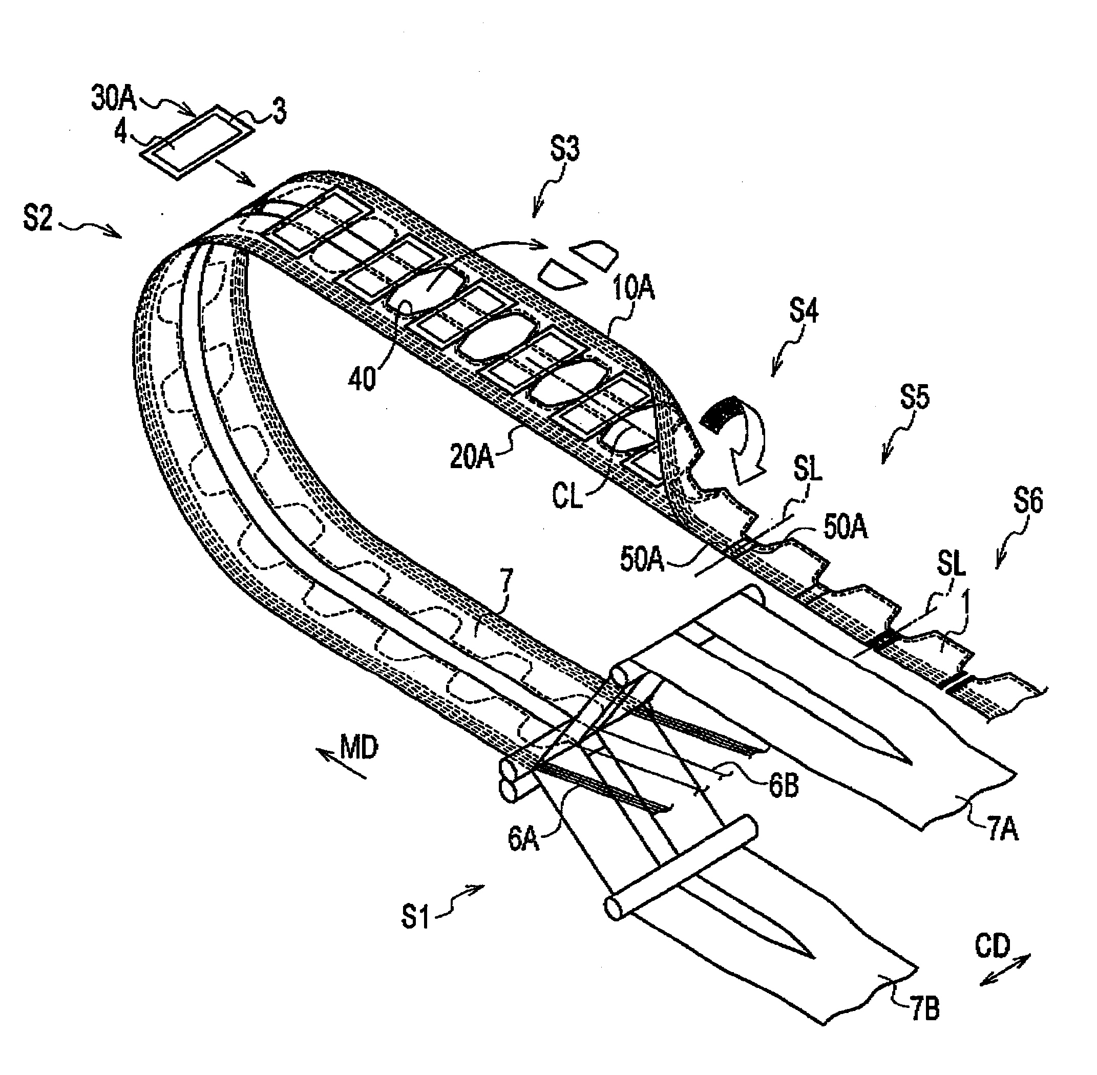
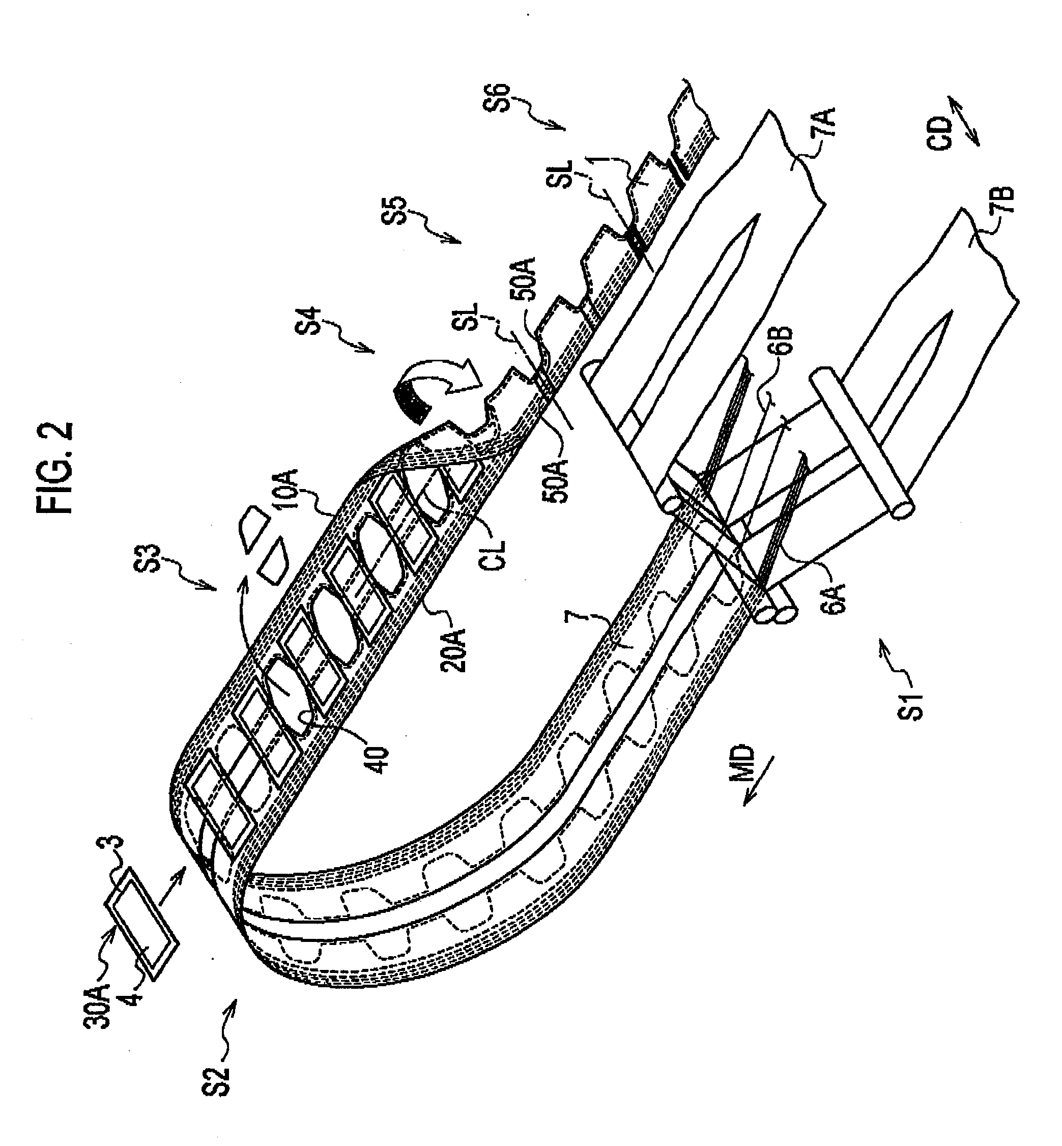
[0062]Note that one or more of the conveyor apparatuses 100 can be used in any one and / or between any pair of the steps (S1 to S6), and thus a description will be given, as an example, for the conveyor apparatus 100 which is used between the leg-surrounding opening forming step S3 and the folding step S4.

[0063]As shown in FIGS. 3 and 4, the conveyor apparatus 100 conveys the web 7 while sucking and holding the web 7 on a belt 110. Specifically, the conveyor apparatus 100 includes the belt 110, a drive mechanism 120 and a suction mechanism 130.

[0064]The belt 110 is an endless belt rotating around multiple rollers of the drive mechanism 120 (for example, a drive roller 121 and unillustrated rollers). A configuration of the belt 110 will be d...

modified examples

[0101]The belt 110 according to the first embodiment described above may be modified as follows. Note that the description will be provided mainly for the differences from the foregoing description, with the same or reference signs denoting the same or similar elements.

modified example 1

[0102]First, a configuration of a belt 210A according to a modified example 1 is explained with reference to FIG. 6 (a) and FIG. 6 (b) which are top views of a belt 210A in various configurations according to the modified example 1.

[0103]In the first embodiment, each second wire 114B is woven alternately over every second one then under the next one of the first wires 114A.

[0104]By contrast, in the modified example 1, each second wire 114B is woven over every two then under the next two of the first wires 114A, as shown in FIG. 6 (a).

[0105]Alternatively, each second wire 114B may be woven under every three then under the next three of the first wires 114A, as shown in FIG. 6 (b).

[0106]Generally speaking, each first wire 114A may be woven over N of the second wires 114B and then under the next M of the second wires 114B, where M and N are integers greater than 1 and M is the same of different from N. Similarly, each second wire 114B may be woven over P of the first wires 114A and the...


PUM

PropertyMeasurementUnit
diameteraaaaaaaaaa
diameteraaaaaaaaaa
stretchableaaaaaaaaaa

Abstract

In a conveyor apparatus (100), a belt (110) is provided with a plurality of suction portions (111) penetrating the belt (110). The belt (110) includes lifting portions (113) each of which is provided between the suction portions (111) adjacent in a cross direction (CD) and lifts from edge portions (112) forming the suction portions (111). The plurality of suction portions (111) adjacent to each other across the lifting portions (113) communicate with each other, when a web (7) is sucked and held on the belt (110). The suction portions (111) located at endmost portions (110A) in the cross direction (CD) of the belt (110) communicate with the outside, when the web (7) is sucked and held on the belt (110).

Description

TECHNICAL FIELD[0001]The present disclosure relates to a conveyor apparatus for conveying an air-permeable continuous web while sucking and holding the web on an endless belt rotating around multiple rollers, and to a method of manufacturing an absorbent article using such a conveyor apparatus.BACKGROUND ART[0002]A method of manufacturing an absorbent article such as a pants-type diaper, a sanitary napkin and a panty liner is implemented in an assembly line.[0003]For instance, a continuous web including top sheets and bottom sheets to form absorbent articles is conveyed under tension in a conveyance direction of the web by a conveyor apparatus.[0004]Then, component members such as a gather (stretchable member) and a waterproof film are placed on the web being conveyed under tension in the conveyance direction.[0005]Meanwhile, the web might stretch or contract in a cross direction (so-called width direction of the web) perpendicular to the conveyance direction, where a stretchable co...

Claims


Application Information

Patent Timeline
Patent Type & Authority Applications(United States)
IPC IPC(8): B65H20/12B65G23/19
CPCA61F13/15764B65H20/06B65H20/10B65H2801/57B65H2301/51214B65H2301/44322B65H2301/44336
Inventor YAMAMOTO, HIROKI
Owner UNI CHARM CORP
Features
  • R&D
  • Intellectual Property
  • Life Sciences
  • Materials
  • Tech Scout
  • Unparalleled Data Quality
  • Higher Quality Content
  • 60% Fewer Hallucinations
Learn More