Method and device for checking the referencing of measuring heads in a chassis measuring system

a chassis and measuring system technology, applied in the field of chassis measurement, can solve problems such as measuring errors in desired target variables, and achieve the effects of improving accuracy, increasing detection reliability, and keeping the relative position of the measuring heads constan

Active Publication Date: 2011-03-10
BEISSBARTH AUTOMOTIVE TESTING SOLUTIONS GMBH
View PDF20 Cites 1 Cited by
  • Summary
  • Abstract
  • Description
  • Claims
  • Application Information

AI Technical Summary

Benefits of technology

[0015]Through the method according to the present invention, the referencing of the chassis measuring system may be checked rapidly and precisely on the basis of a relative movement between the measuring heads and the vehicle in the measuring field of the measuring heads, for example, by moving the vehicle past the measuring heads. The precision of the chassis measuring following the referencing is thus improved, without a noticeably longer time being required for performing the measuring. No additional hardware is necessary in order to perform the referencing according to the present invention, so that the present invention may be implemented cost-effectively. The assumption that orientations which are measured once during the measurement or during the service life of the measuring system remain constant may be monitored. If a change in the position parameters is noted, a message may be given to the user, and the changed orientation may be corrected.
[0032]In one specific example embodiment, the device additionally has a movement device, which is implemented to execute a relative movement between the system of measuring heads, on the one hand, and the vehicle, on the other hand, between the initial position and the final position during operation, the relative position of the measuring heads to one another being kept constant. It is thus possible to execute a defined and controlled relative movement between the system of measuring heads and the vehicle. In particular, accidents due to an uncontrolled movement of the vehicle may be avoided.

Problems solved by technology

Deviations from these assumptions directly result in a measuring error in the desired target variables.

Method used


Image

  • Method and device for checking the referencing of measuring heads in a chassis measuring system
  • Method and device for checking the referencing of measuring heads in a chassis measuring system

Examples


Embodiment Construction

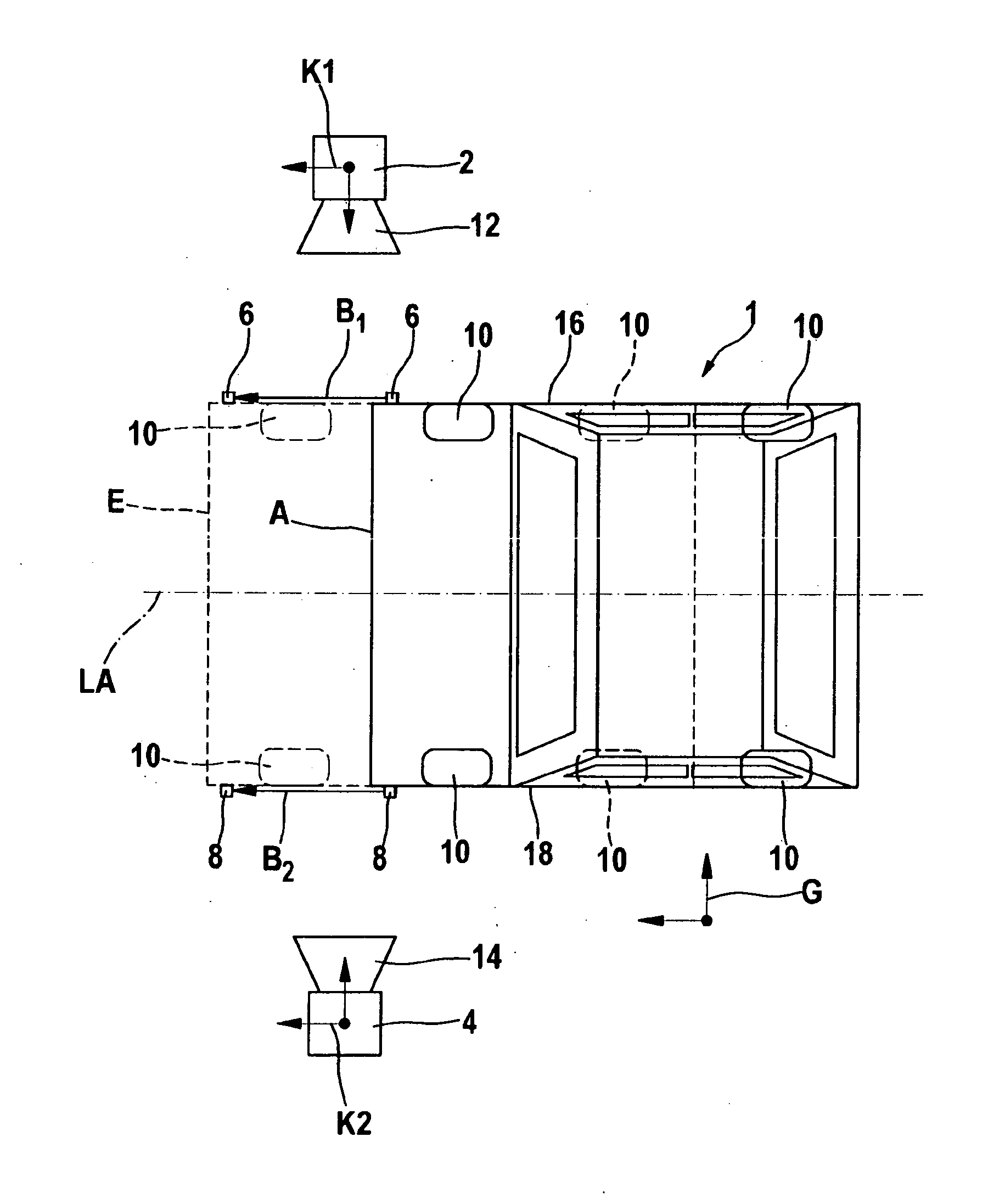
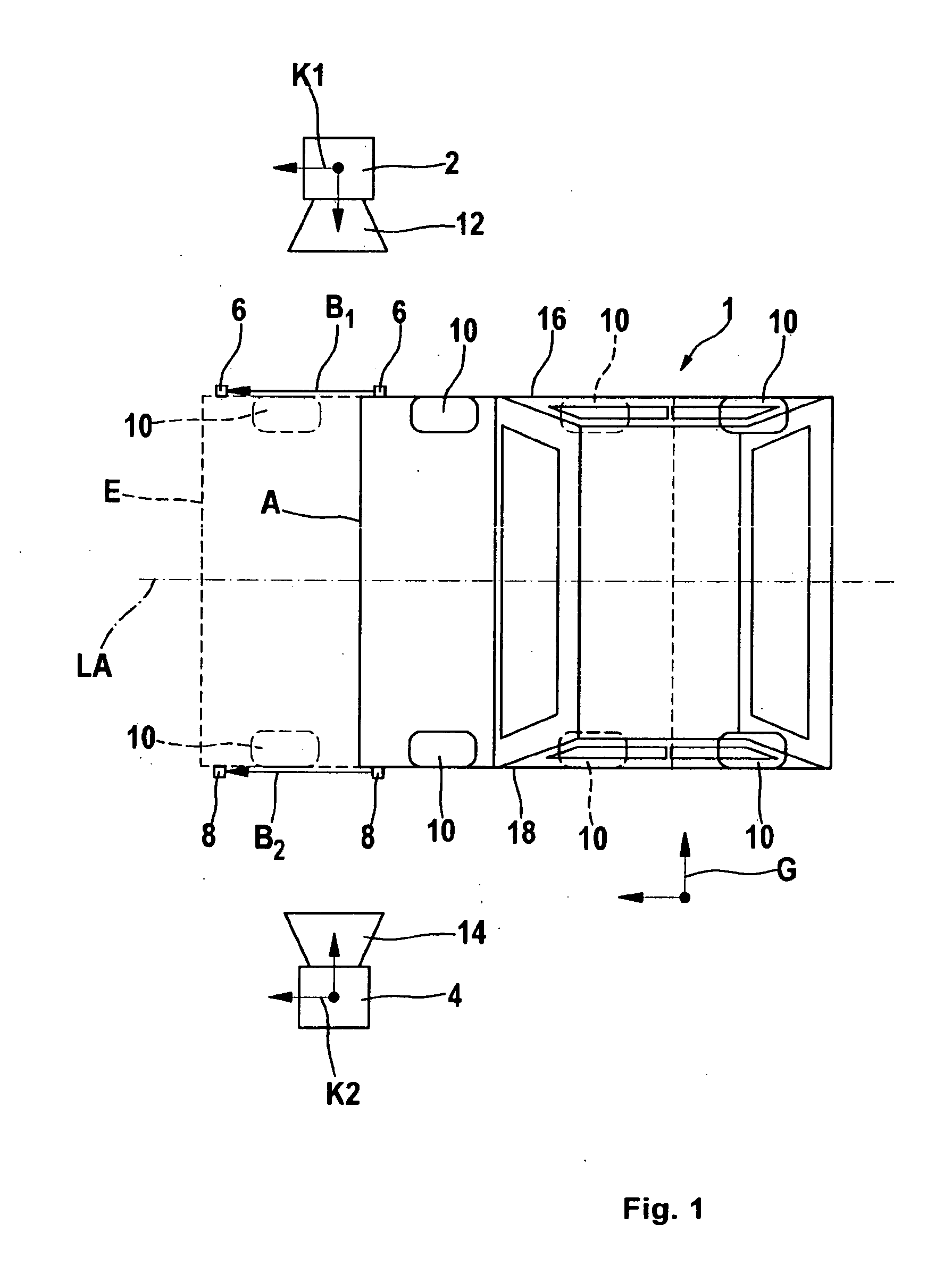
[0035]FIG. 1 shows a schematic top view of the outline of a vehicle 1, in an initial position A (solid line) at point in time ti and in a final position E (dashed line) at point in time ti+1. For simplification, only two points in time are shown in the figure. In addition to the outline of the chassis of vehicle 1, four wheels 10 are schematically shown. Vehicle 1 is situated in such a way that its front side is shown on the left in the figure and its rear side on the right. Final position E is located horizontally on the left from initial position A. The movement between initial position A and final position E occurs parallel to horizontal longitudinal axis LA of vehicle 1. Vehicle 1 is not rotated during the movement shown here.

[0036]One measuring head 2, 4 is situated in each case on the left and right of vehicle 1 in the movement direction, which each have a camera 12, 14, which is directed toward vehicle 1. A measuring target 6, 8 is attached on each of side 16, 18 of vehicle 1...


PUM


Abstract

A method for checking the referencing of at least two measuring heads of a contactless chassis measuring system includes: detecting at least one geometry detail of a vehicle using the measuring heads; determining an initial position of the geometry detail in the coordinate system associated with each measuring head; transforming the initial position into a shared coordinate system; executing a relative movement between the measuring heads and the vehicle; determining a final position of the at least one geometry detail in the coordinate system associated with each measuring head; transforming the final position of the geometry detail into the shared coordinate system; determining the movement vectors from the difference between the final position and the initial position of the at least one geometry detail; checking the movement vectors for coincidence.

Description

BACKGROUND OF THE INVENTION[0001]1. Field of the Invention[0002]The present invention relates to chassis measuring, and in particular a method and a device for checking the referencing of measuring heads of a contactless chassis measuring system.[0003]2. Description of Related Art[0004]In optical chassis measuring, for example, the measuring of toe and camber on motor vehicles, measuring heads are used, which each detect one wheel or possibly the wheels of one vehicle side. The position of wheel axes, rotational axes, wheel centers, or rotational centers are calculated from the measured values and used for determining the toe and camber.[0005]A fundamental requirement in a system for, chassis and axle measuring is that the measured values of all measuring heads are provided in a shared coordinate system (“reference system”) or are transformed into such a shared coordinate system. The characteristic variables of the geometrical position of the measuring heads among one another, such ...

Claims


Application Information

Patent Timeline
Patent Type & Authority Applications(United States)
IPC IPC(8): G01M17/04
CPCG01B11/275G01B11/26
Inventor ABRAHAM, STEFFENMUHLE, DANIEL
Owner BEISSBARTH AUTOMOTIVE TESTING SOLUTIONS GMBH
Why Eureka
Try Eureka