
Display device

a display device and display technology, applied in the field of display devices, can solve the problems of inability to use encoding in application realms, easy legibility, etc., and achieve the effect of convenient perceptibility

Active Publication Date: 2011-03-10
VEGA GRIESHABER GMBH & CO
View PDF3 Cites 2 Cited by
  • Summary
  • Abstract
  • Description
  • Claims
  • Application Information

AI Technical Summary

Benefits of technology

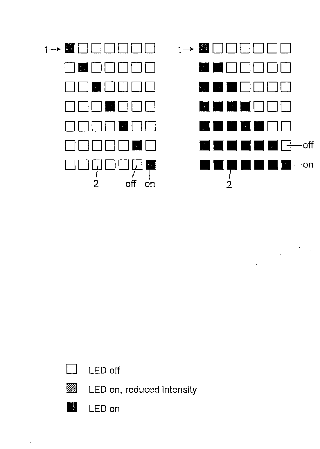
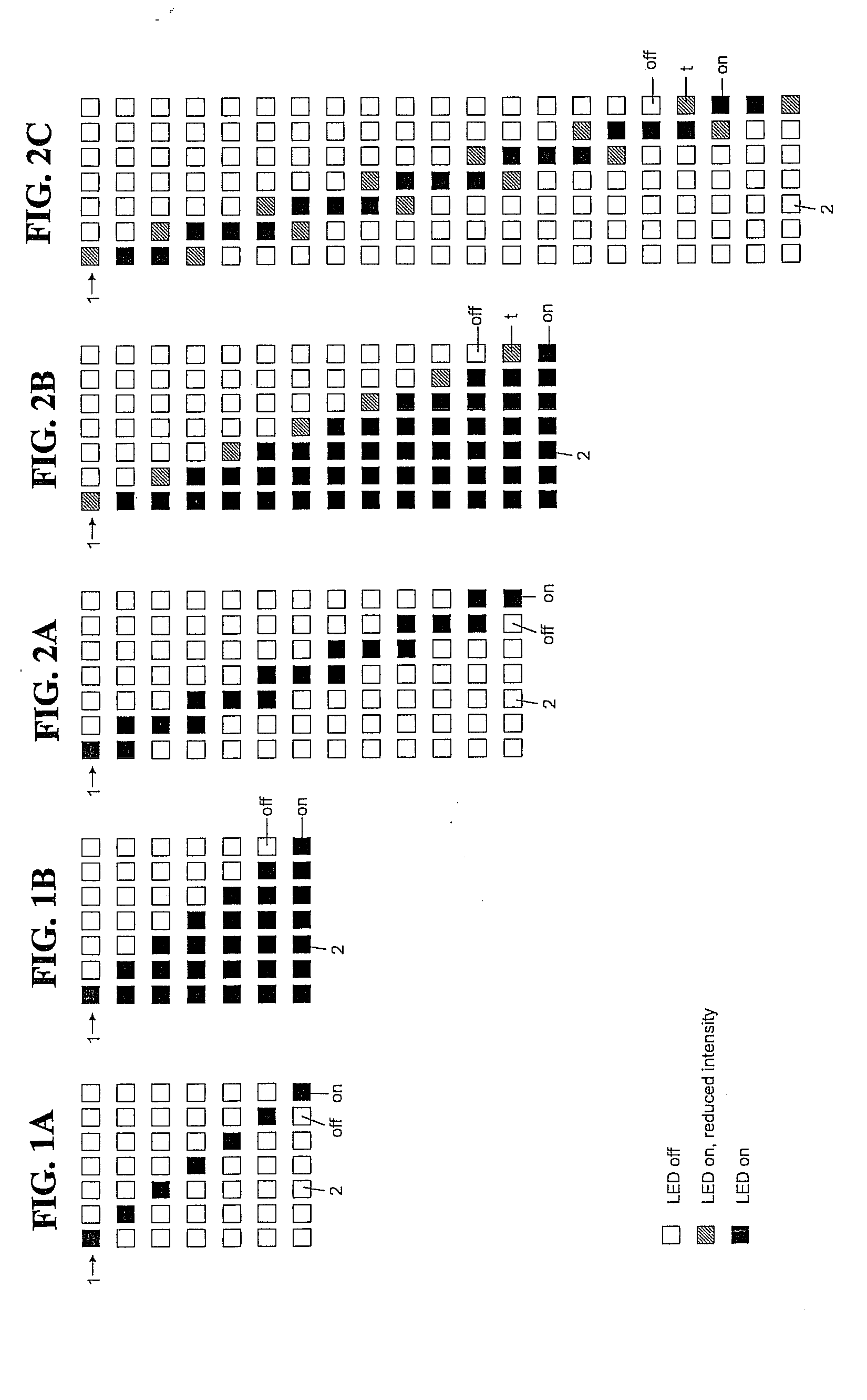
[0013]The present invention thus, on the one hand, makes use of the easy legibility of progress meters and, on the other hand, makes it possible to represent intermediate values by the activating of a preceding or succeeding display element. If an individual value being represented is represented by the activation of an individual display element, intermediate states between the value being represented and a succeeding value can be represented by simultaneous activation of the display element assigned to the value being represented and the succeeding display element. A display with, say, seven display elements can thus show, in addition to the seven formerly representable values, six additional intermediate values, so that in all a display of 13 different conditions is possible.
[0017]Such a display device has the advantage that one can recognize at a glance, thanks to the number of light emitting diodes (LEDs), the region in which the value being displayed is located; and, furthermore, one instantly recognizes, by a direct comparison, whether an additional light emitting diode (LED) is operating at full or half brightness.
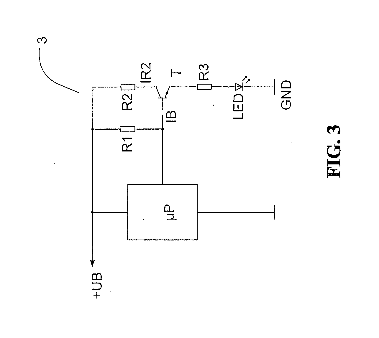
[0025]In addition to an “on state” at the current rating and an “off state” at 0 amperes, a third state with around half brightness at around half current rating is thereby achieved. The third state, on the one hand, is easily perceptible as compared to a light emitting diode (LED) that is switched off, and on the other hand it can also be well distinguished from a light emitting diode (LED) operating at the current rating.

Problems solved by technology

However, such an encoding comes at the expense of easy legibility, so that encoding cannot be used in application realms where a fast, precise and easy legibility needs to be assured.
What is not appreciated by the prior art is the problem of providing a display device which assures an easy, reliable and fast legibility, yet enables the displaying of an enlarged range of values.

Method used


Image

  • Display device
  • Display device
  • Display device

Examples


Embodiment Construction

[0041]Reference will now be made in detail to several embodiments of the invention that are illustrated in the accompanying drawings. Wherever possible, same or similar reference numerals are used in the drawings and the description to refer to the same or like parts or steps. The drawings are in simplified form and are not to precise scale. For purposes of convenience and clarity only, directional terms, such as top, bottom, up, down, over, above, and below may be used with respect to the drawings. These and similar directional terms should not be construed to limit the scope of the invention in any manner. The words “connect,”“couple,” and similar terms with their inflectional morphemes do not necessarily denote direct and immediate connections, but also include connections through mediate elements or devices.

[0042]Referring now to FIGS. 2A through 2C, each shows a display device 1 with seven display elements 2 arranged in the form of a bar (shown horizontally here but not limited...


PUM


Abstract

Display device, with a plurality of display elements arranged in the shape of a bar, wherein each display element can represent at least one first display state (off) and one second display state (on), and a value being shown can be indicated by the second display state (on) of at least one display element assigned to the value, so that an intermediate value between the value being displayed and a succeeding or preceding value can be represented by activating the preceding or succeeding display element.

Description

CROSS REFERENCE TO RELATED APPLICATIONS[0001]This application claims priority from European Patent Application Serial No. EP 09 011 425.7, filed Sep. 7, 2009, and U.S. Provisional Patent Application Ser. No. 61 / 241,451, filed Sep. 11, 2009, the entire contents of each of which is herein incorporated fully by reference.FIGURE FOR PUBLICATION[0002]FIG. 3BACKGROUND OF THE INVENTION[0003]1. Field of the Invention[0004]The present invention relates to a display device. More specifically, the present invention relates to a display device which ensures ease of use and reliable and legible display with an enlarged range of values.[0005]2. Description of the Related Art[0006]Such display devices are known from the prior art as “progress meters”. The known progress meters consist of a number of bar-shaped display elements arranged in a row, while either an individual display element assigned to the value or all display elements up to the display element assigned to the value are activated to ...

Claims


Application Information

Patent Timeline
Patent Type & Authority Applications(United States)
IPC IPC(8): G09G5/10G09G3/04G09G3/14H05B44/00
CPCG01R13/406H05B37/029H05B33/0845G09G3/14H05B45/10H05B47/155
Inventor WOHRLE, SIEGBERTSCHULTHEISS, DANIELFEHRENBACH, JOSEFDECK, THOMASFISCHER, MICHAEL
Owner VEGA GRIESHABER GMBH & CO
Learn More