Cryogenic liquid cylinder manifold

a technology of cryogenic liquid cylinder and manifold, which is applied in the direction of fluid pressure control, container discharge methods, instruments, etc., can solve the problems of waste of liquid/gas, multiple joints between components, and process incurring an associated labor cost, so as to reduce the number of potential leak paths, reduce the number of throughput, and eliminate the effect of high labor cost and/or long assembly tim

Inactive Publication Date: 2011-03-17
TYCO VALVES & CONTROLS LP
View PDF1 Cites 9 Cited by
  • Summary
  • Abstract
  • Description
  • Claims
  • Application Information

AI Technical Summary

Benefits of technology

[0010]The disclosed manifold packages or unitizes a plurality of valves required for liquid cylinder operation into a single unit, thus eliminating the need for labor to purchase and pipe together all the needed valves and components separately. This eliminates typically high labor cost and/or long assembly time, reduces throughput, reduces the number of potential leak paths, and red...

Problems solved by technology

One problem with current arrangements is that each of these multiple individual components must each be fabricated, sourced, and assembled into a final operational unit.
Each step in this process incurs an associated labor cost.
Another problem is ...

Method used


Image

  • Cryogenic liquid cylinder manifold
  • Cryogenic liquid cylinder manifold
  • Cryogenic liquid cylinder manifold

Examples


Embodiment Construction

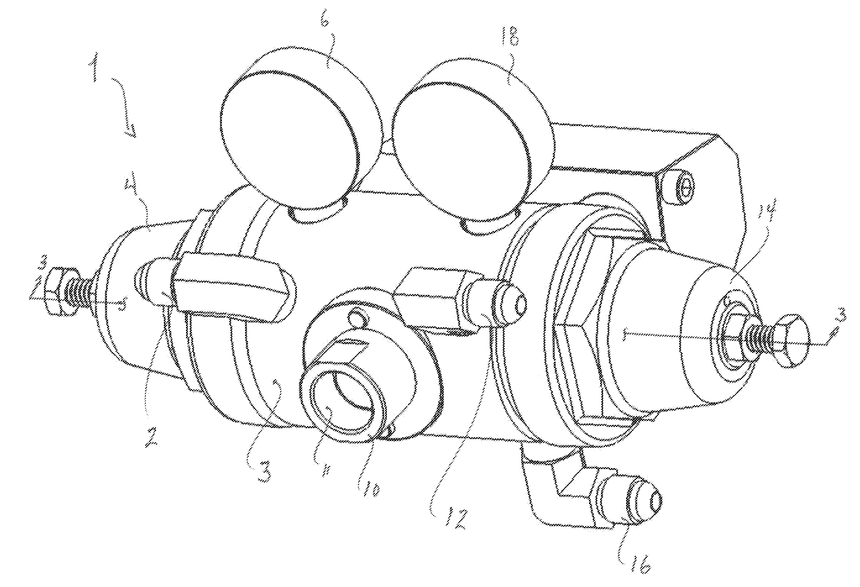
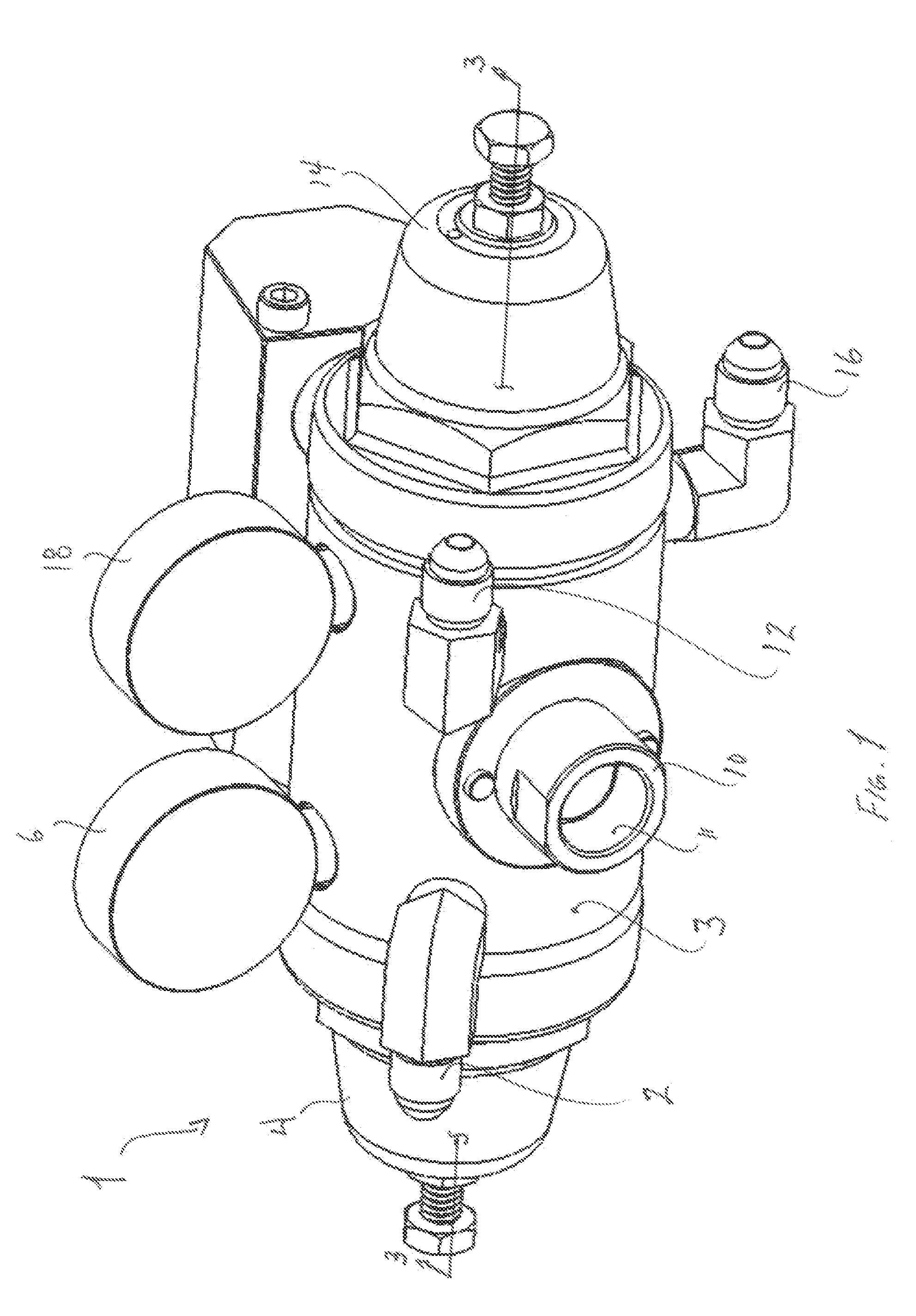
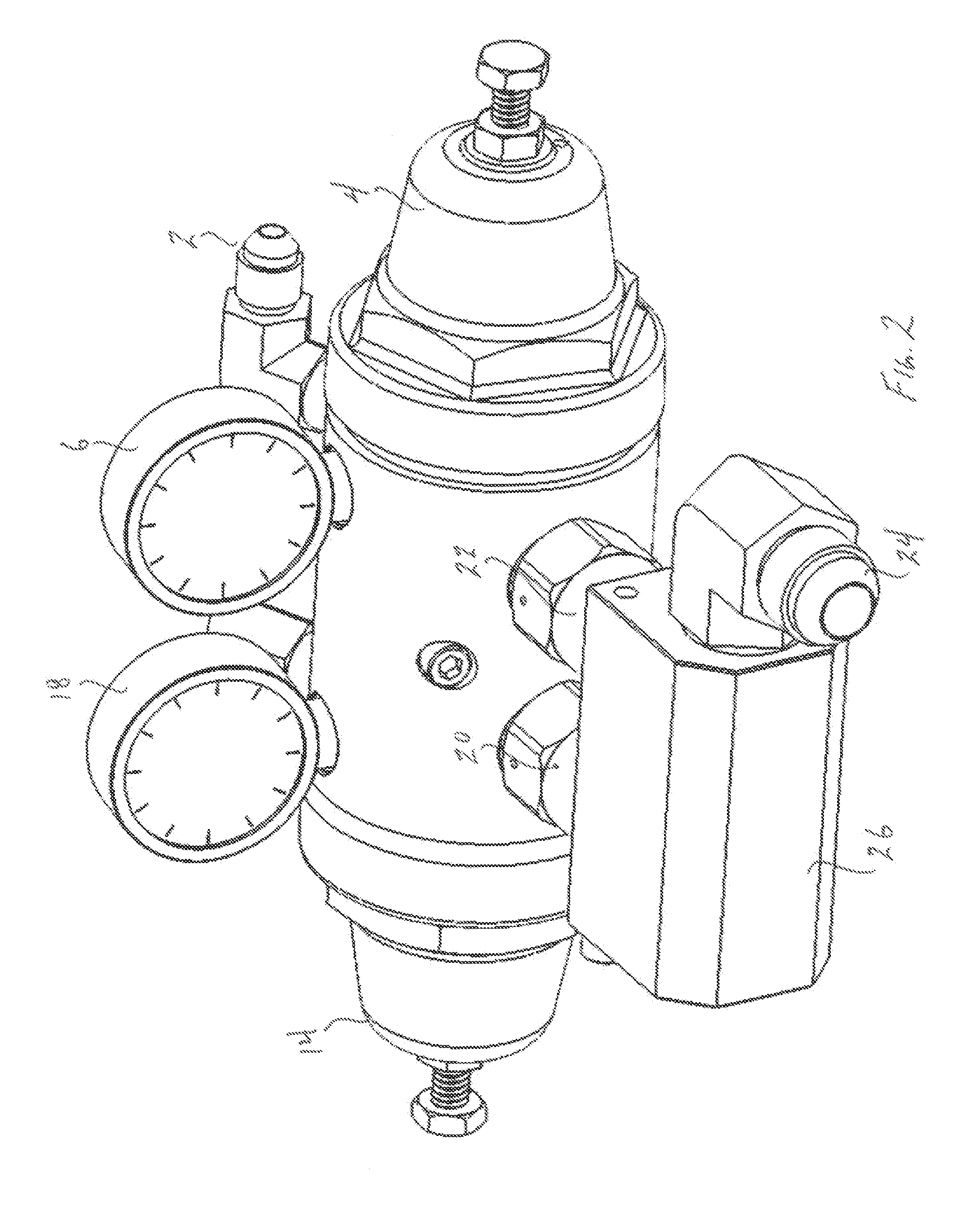
[0021]A manifold is disclosed for the control of liquid cylinder pressures for liquid or gaseous compositions. In one embodiment, the manifold is a CO2 cryogenic liquid cylinder pressure control manifold for use in the beverage industry. The manifold packages or unitizes together a plurality of valve components required for liquid cylinder operation into one unit, thus eliminating the need for labor to purchase and pipe together all of the needed valves separately.

[0022]The manifold 1 generally comprises a unitary body 3 to which a plurality of fittings, valves and gauges are coupled. The fittings, valves and gauges are interconnected, as will be described in greater detail, via internal passageways that are machined or otherwise formed in the manifold.

[0023]Referring to FIGS. 1-3, the manifold 1 includes a pressure build regulator 4 useful for building pressure in a liquid storage cylinder or tank (not shown). The storage cylinder is attached to the manifold through a pressure buil...


PUM


Abstract

A cryogenic liquid cylinder pressure control manifold is disclosed. The manifold includes, in a unitary arrangement, a pressure build regulator, a pressure build inlet fitting, a pressure build regulator, NPT adapter fitting, a check valve, and a cylinder pressure gauge. The disclosed manifold eliminates various threaded connections associated with prior devices, thus providing a more reliable device having less likelihood to leak in service. The disclosed manifold also reduces labor costs associated with assembling prior systems which are composed of a plurality of different individual components. In one embodiment, the disclosed manifold is employed as a cryogenic CO2 manifold for use in the beverage industry.

Description

CROSS-REFERENCE TO RELATED APPLICATIONS[0001]This is a non-provisional application of pending U.S. provisional patent application Ser. No. 61 / 241,726, filed Sep. 11, 2009, the entirety of which provisional application is incorporated herein by reference.BACKGROUND OF THE INVENTION[0002]1. Field of the Invention[0003]Embodiments of the invention generally relate to the field of cryogenic liquid cylinder pressure control manifolds, and more particularly to a CO2 cryogenic liquid cylinder pressure control manifold for the beverage industry.[0004]2. Discussion of Related Art[0005]Cryogenic liquids, that is, liquids having a boiling point generally below −150° F. at atmospheric pressure, are used in a variety of applications. Such cryogens are typically stored as liquids, since one volume of liquid produces many volumes of gas (600-900 volumes of gas per one volume of liquid) when the liquid is permitted to vaporize and warm to ambient temperature. In one common use, cylinders filled wit...

Claims


Application Information

Patent Timeline
IPC IPC(8): F17C13/04F17C9/02
CPCF17C13/04F17C2270/05F17C2205/0335F17C2205/0373F17C2205/0382F17C2205/0385F17C2221/011F17C2221/013F17C2221/014F17C2221/016F17C2223/0161F17C2223/033F17C2227/0383F17C2227/0393F17C2250/043F17C2205/0326Y10T137/0396Y10T137/87917
Inventor OSTEEN, WILLIAM CLINTONHAMM, MARK K.
Owner TYCO VALVES & CONTROLS LP
Why Eureka
Try Eureka