
Airbag cover and airbag device

Inactive Publication Date: 2011-03-17
ASHIMORI INDS
View PDF8 Cites 9 Cited by
  • Summary
  • Abstract
  • Description
  • Claims
  • Application Information

AI Technical Summary

Benefits of technology

[0009]According to the present invention, a decorative member can be readily attached to an airbag cover of an airbag device, and it is possible to enhance workability of the attachment. In addition, a decorative member can be securely attached and held to an airbag cover, and it is possible to increase the degree of freedom of the design on the shape of the decorative member.

Problems solved by technology

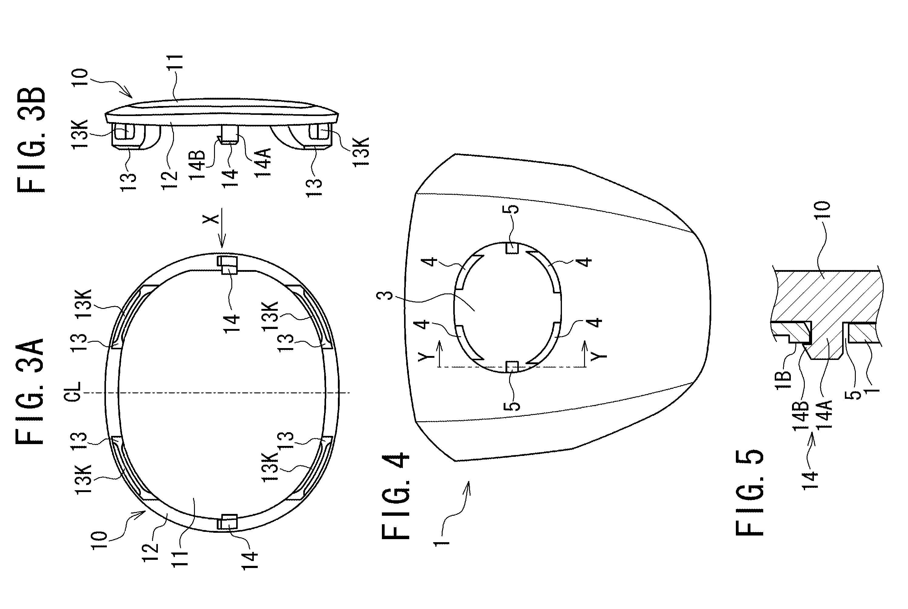
In the airbag device, since the catching part, which includes an area for a plurality of legs arranged at the decorative member, must be rotatable, the size and shape of the catching part are limited.
In addition, since the plurality of legs extends along the circumferential direction, the shape of the decorative member is limited to a circular form such as a ring or a disk, which impairs the degree of freedom of the design.
In the conventional airbag device, since the decorative member is fixed to the cover body by rotating the catching part in one direction to engage the retainers to the legs, a rotative force against the catching part in the opposite direction may cause the decorative member to disengage the decorative member from the cover.
Furthermore, in order to compressively clip the cover body by the decorative member and the catching part after the decorative member is attached, the catching part is forced to be rotated while the decorative member is strongly pressed against to the cover body during the attaching work, which may cause a surface of the decorative member or the back face of the cover body to be damaged.
In addition, the catching part should be rotated by a strong force with a special jig while the decorative member is pressed during the attaching work, resulting in difficulty in attachment with low workability.

Method used


Image

  • Airbag cover and airbag device
  • Airbag cover and airbag device
  • Airbag cover and airbag device

Examples


Embodiment Construction

[0018]An embodiment of the present invention is described below with reference to the drawings.

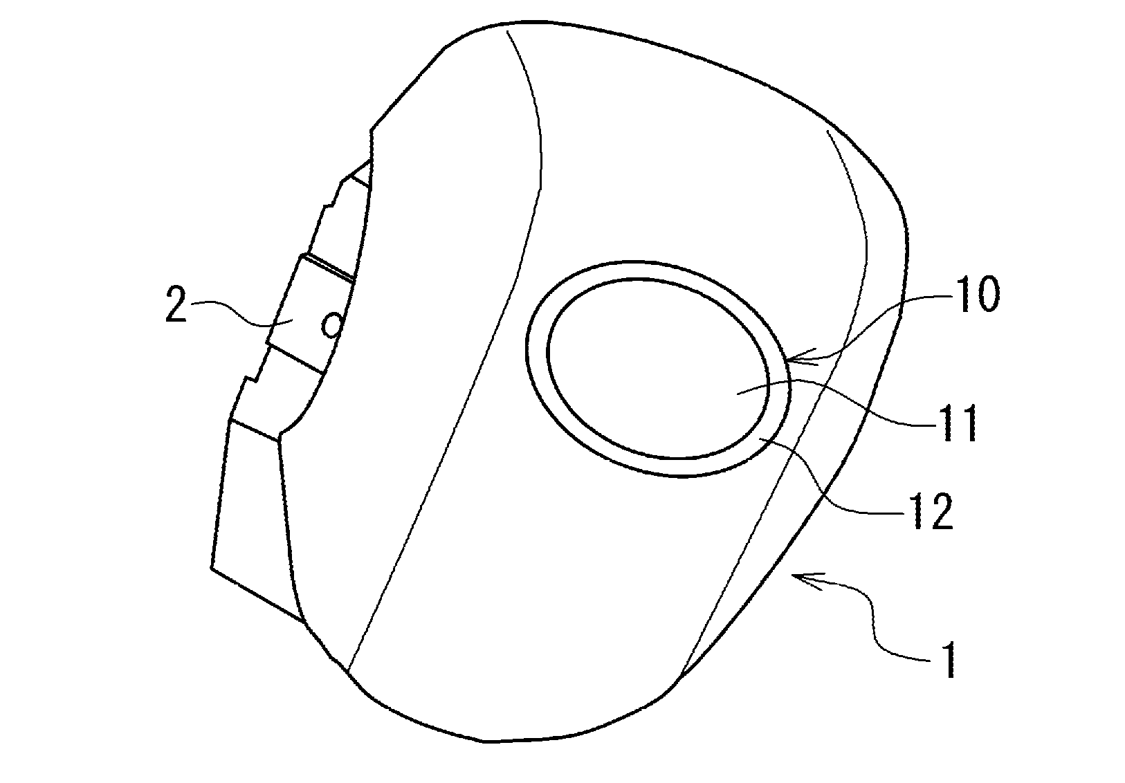
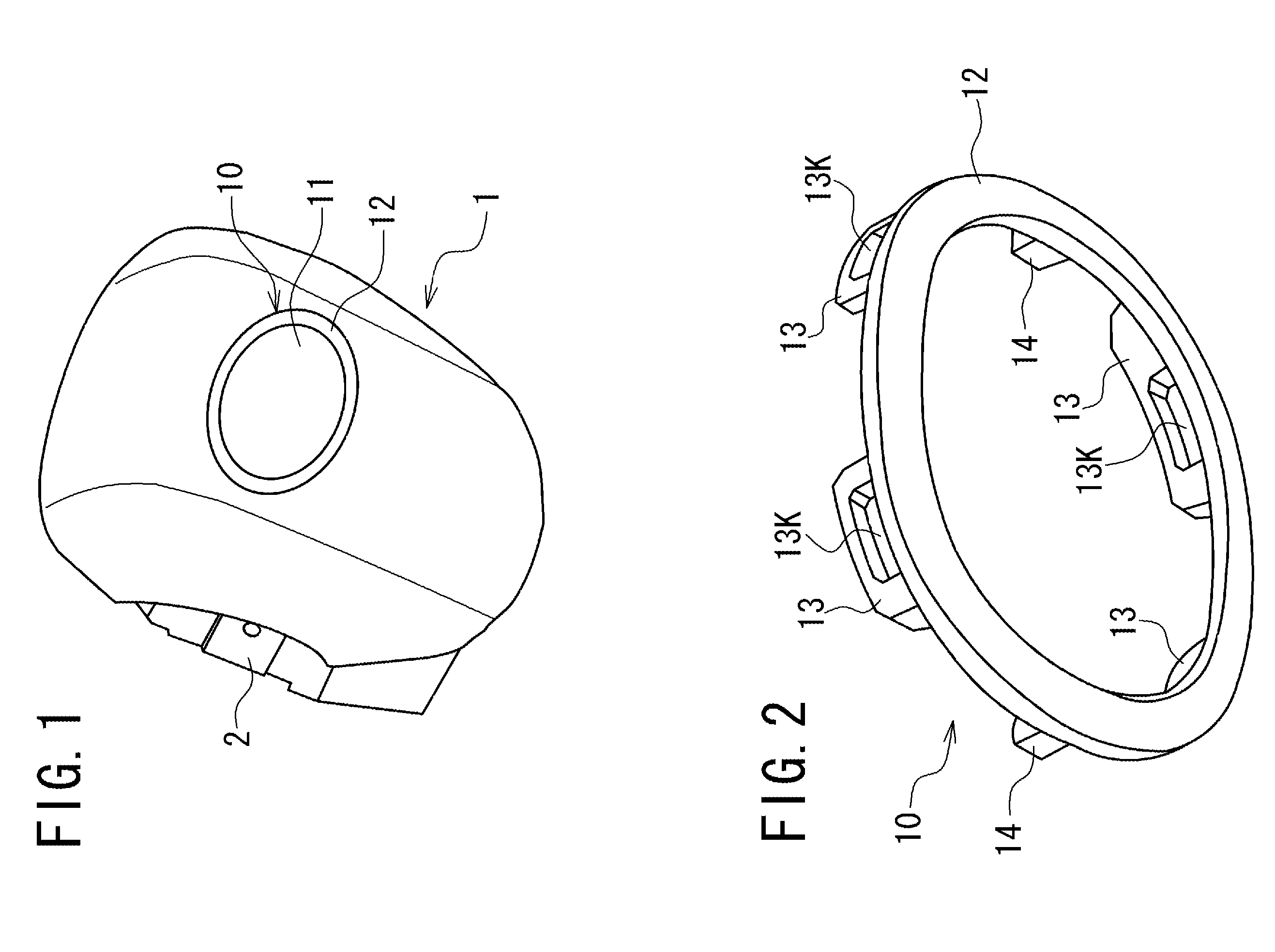
[0019]An airbag device according to the embodiment is an airbag device used for, for example, a driving seat, a passenger seat, or a side of a vehicle, and includes an airbag that can be inflated and deployed and an inflator that generates gas to be supplied to the airbag in the event of emergency or impact detection. The airbag device also includes an airbag cover having a decorative member attached on the front face. The folded airbag and the inflator are put in the airbag cover, and the airbag device is installed in a vehicle such that the vehicle interior side of the airbag is covered with the airbag cover.

[0020]Taking an airbag device to be mounted on a steering wheel of a vehicle as an example, an airbag cover having the decorative member is described below. Throughout the description of the airbag cover mounted to a vehicle, the back face refers to a face adjacent to the airbag and ...


PUM


Abstract

A decorative member can be readily attached to an airbag cover of an airbag device and attaching workability is enhanced. A decorative member 10 is attached to an attaching part 3 of an airbag cover 1, and engaging projections 13 of the decorative member 10 pass through through-holes in the airbag cover 1 to the back face 1B of the airbag cover 1. A holding member 20 is bent and pressed against the airbag cover 1 side, so that the engaging sections 21 are moved from a state where they are approached to each other between the engaging projections 13, to the direction in which the engaging sections 21 separate from each other. Consequently, the engaging sections 21 are inserted to engaging holes 13K to be engaged with the engaging projections 13. The holding member 20 allows the decorative member 10 to be attached to the airbag cover 1 through the engaging projections 13.

Description

TECHNICAL FIELD[0001]The present invention relates to an airbag cover of an airbag device to installed in vehicles and, in particular, to an airbag cover having a decorative member and an airbag device including the airbag cover.BACKGROUND ART[0002]In order to protect passengers on a driving seat and a passenger seat in the event of a vehicle collision or emergency, cars having an airbag device including an inflatable and deployable airbag, for example, in a steering wheel or an instrumental panel are in widespread use. Since the airbag cover covering the airbag of the airbag device is usually installed, for example, at a front face or a sidewall facing a passenger in the interior of a car, it comes under passenger's observation. Accordingly, the airbag cover requires an ornamental design or decoration in addition to the passenger protecting function. So, until now, a decorative member having a decorative pattern such as logo or car's name is attached to the airbag cover to improve ...

Claims


Application Information

Patent Timeline
IPC IPC(8): B60R21/20B60R21/203B60R21/215
CPCB60R2021/21543B60R21/21656B60R13/005
Inventor HAYASHI, NAOYA
Owner ASHIMORI INDS
Learn More