
Vehicle door mirror

Active Publication Date: 2020-10-29
HONDA LOCK MFG CO LTD +1
View PDF0 Cites 0 Cited by
  • Summary
  • Abstract
  • Description
  • Claims
  • Application Information

AI Technical Summary

Benefits of technology

The present invention is aimed at providing a vehicle door mirror with effective vibration suppression without increasing the cost. The invention includes a vibration suppression arm that is integrated with the retractable mirror unit, and a housing fastening part is formed on the tip end of the arm. This eliminates the need for a separate vibration suppression member and makes mounting easier and cost-effective. The arm extends away from the fastening parts to attenuate vibes transmitted from the side door and suppress small vibrations of the mirror housing. The arm also has a bent portion to further attenuate vibration transmission and to prevent interference with the mirror angle adjustment unit. The base part of the arm is connected to the unit constituent member with a screw, which enhances the strength of the connection. Overall, the invention provides a solution for effective vibration suppression without adding extra cost or complexity to the vehicle door mirror system.

Problems solved by technology

However, in the structure disclosed in Japanese Patent No. 4924482, the reinforcing plate, which is a separate member from an electric retraction unit, is mounted on the mirror housing, it is therefore necessary to carry out an operation of mounting the reinforcing plate on the mirror housing in addition to an operation of mounting the electric retraction unit thereon, and not only is the workability degraded, but also the production cost is increased.
Moreover, since some of the plurality of locations via which the reinforcing plate is fastened to the mirror housing are fastened to the mirror housing by being fastened together with the electric retraction unit, if the fastening part via which it is fastened together therewith becomes loose, there is a possibility that the vibration suppression force will be decreased.

Method used


Image

  • Vehicle door mirror
  • Vehicle door mirror
  • Vehicle door mirror

Examples


Embodiment Construction

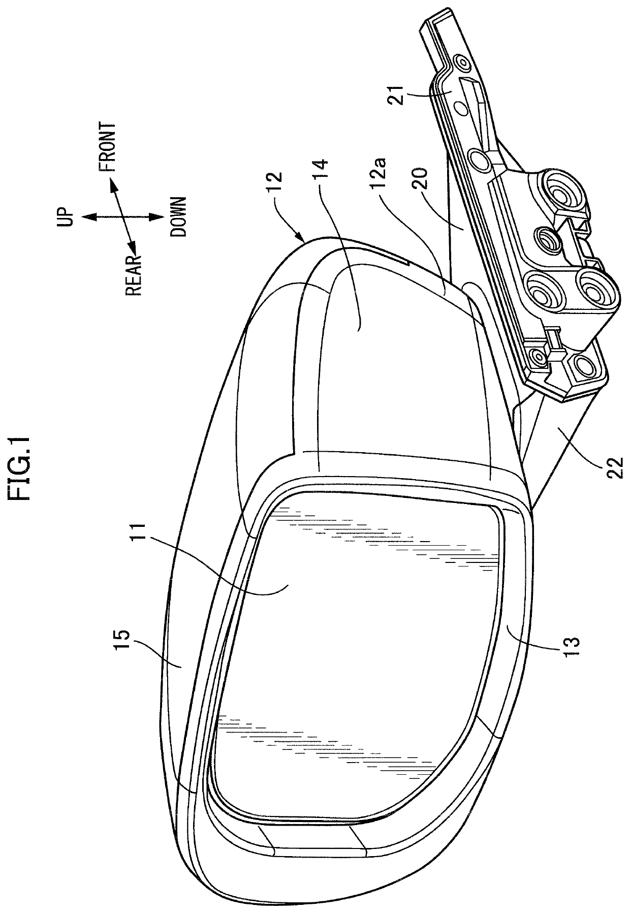
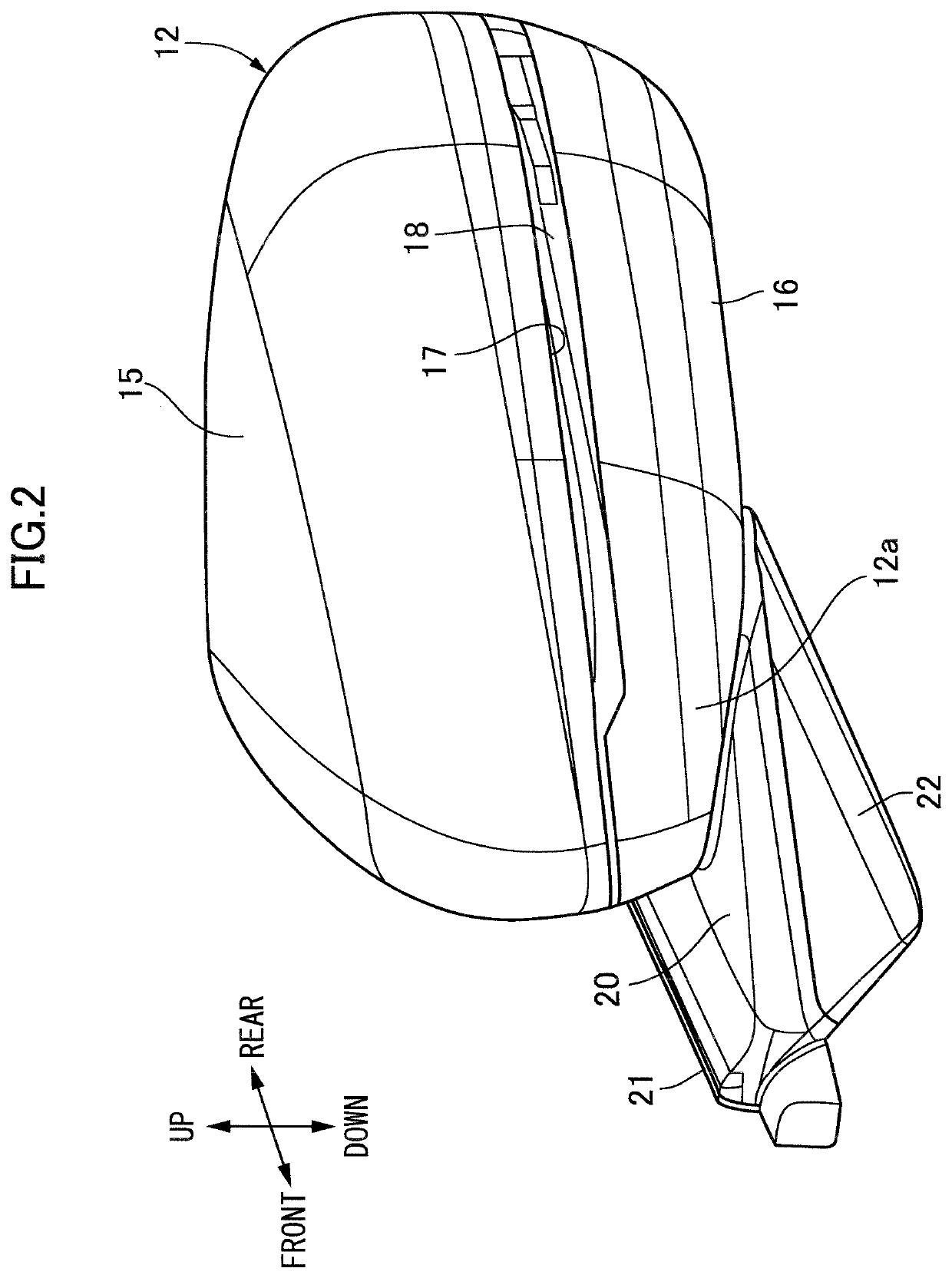
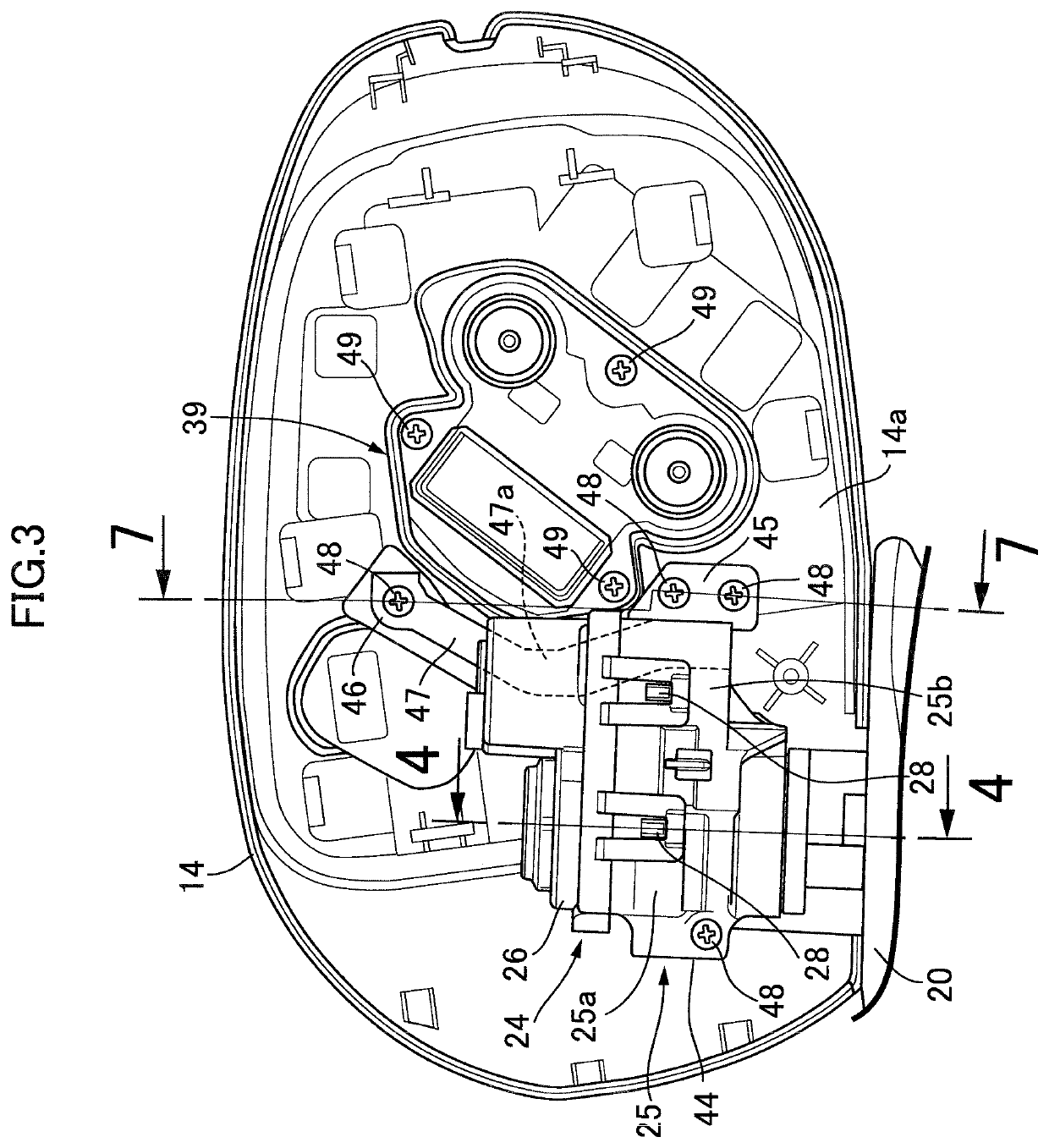
[0021]An embodiment of the present invention is explained below by reference to the attached FIG. 1 to FIG. 7; first, in FIG. 1 and FIG. 2, left and right front side doors in a passenger vehicle are provided with a mirror housing 12, into which a mirror 11 for viewing to the rear of the vehicle is fitted, so that the mirror housing 12 can pivot between a raised position in which it projects sideways from the front side door and a retracted position in which it is retracted toward the front side door.

[0022]The mirror housing 12 is formed from a housing main body 14, made of a resin, having a mirror housing recess 13 housing the mirror 11, an upper cover 15, made of a resin, covering the housing main body 14 from a direction opposite to the mirror 11, and a lower cover 16, made of a resin, covering a lower part of the housing main body 14 from below; a side turn lamp 18 is housed within the mirror housing 12, part of the side turn lamp 18 facing a slit 17 for the lamp formed between t...


PUM


Abstract

In a vehicle door mirror, an electric retraction unit is disposed between a mirror housing and a shaft pivotably supporting a base end part of the mirror housing, and at least three housing fastening parts are fastened to the mirror housing and provided integrally with a unit constituent member forming part of the electric retraction unit. A vibration suppression arm part is provided integrally with the unit constituent member and extends in a direction that goes away from at least two of the at least three housing fastening parts. A remaining one housing fastening part of the at least three housing fastening parts is formed in a tip end part of the vibration suppression arm part. Accordingly, the vehicle door mirror can give an effective vibration suppression effect while enhancing the workability and suppressing any increase in the cost.

Description

BACKGROUND OF THE INVENTIONField of the Invention[0001]The present invention relates to a vehicle door mirror comprising a mirror housing that has a mirror housing recess housing a mirror, a base member that is to be mounted on a side door, a shaft that is standingly provided on the base member so as to pivotably support a base end part of the mirror housing, and an electric retraction unit that is disposed between the shaft and the mirror housing so as to pivot the mirror housing around an axis of the shaft, at least three housing fastening parts being fastened to the mirror housing and provided integrally with a unit constituent member forming part of the electric retraction unit.Description of the Related Art[0002]Such a vehicle door mirror is known from for example Japanese Patent No. 4924482, and in this arrangement in order to prevent visibility from being degraded due to chattering in the mirror caused by small vibrations of a mirror housing due to the vehicle traveling, a re...

Claims


Application Information

Patent Timeline
IPC IPC(8): B60R1/074
CPCB60R1/074B60R1/1207B60R1/072
Inventor KENMOCHI, KENJIKAWANO, YUKINORIISHIBASHI, YUKISASAKI, TAKESHIHASHIMOTO, TAKURO
Owner HONDA LOCK MFG CO LTD
Learn More