
Recording apparatus and liquid ejecting apparatus

Inactive Publication Date: 2008-02-21
SEIKO EPSON CORP
View PDF2 Cites 4 Cited by
  • Summary
  • Abstract
  • Description
  • Claims
  • Application Information

AI Technical Summary

Benefits of technology

[0009]An advantage of some aspects of the invention is that, in a case where an optical sensor is used as a sheet detector, the workability in the mounting process of the optical sensor is enhanced and the accuracy in the mount position of the optical sensor is improved.
[0011]According to the first aspect, one of the light-emitting portion and the light-receiving portion constituting the optical sensor that detects passing of the recording medium projects from an outer side of the recording-medium transport path towards the first guide member at a position near a transport reference position of the recording medium. The first guide member has a cutout at least having an opening at the side near the transport reference position of the recording medium and at a side facing the second guide member. The light-emitting portion or the light-receiving portion is disposed within the cutout. Accordingly, when carrying out the assembly process of the recording apparatus, a mounting process of the optical sensor is preliminarily performed, and an attaching process of the first guide member is performed afterwards. In other words, the first guide member is in still its unattached state when the mounting process of the optical sensor is being performed. This enhances the workability in the mounting process of the optical sensor as well as facilitating the adjustment process of the mount position. In addition, the optical sensor can be fixed to a position near the recording-medium transport path, thereby preventing the accuracy in the mount position of the optical sensor from being reduced. Furthermore, the opening of the cutout is covered with a sheet member except for an area where the optical axis of the optical sensor extends. Therefore, when the recording medium passes the opening, the leading end of the recording medium is prevented from getting stuck at the opening. Consequently, this prevents bending of the leading end of the recording medium and also prevents the recording medium from being skewed as a result of the leading end thereof being stuck at the opening.
[0012]In the recording apparatus of the first aspect, the sheet member preferably has flexibility and is provided in the first guide member such that the sheet member is wound around the first guide member to cover the opening facing the second guide member.
[0013]Accordingly, since the sheet member may have flexibility and be provided in the first guide member such that the sheet member is wound around the first guide member to cover the opening facing the second guide member, the sheet member can be simplified in structure and can be provided at low cost. When the first guide member is to be attached to the recording apparatus so that the optical sensor is accommodated within the cutout, even if the optical sensor comes into contact with the sheet member, the optical sensor is prevented from being damaged since the sheet member is flexible.
[0015]Accordingly, since the light-emitting portion and the light-receiving portion may be integrated with each other and the optical sensor may be mounted on the second guide member, the optical sensor can be preliminarily mounted on the second guide member, and the second guide member with the optical sensor mounted thereon can be subsequently attached to the base body of the recording apparatus. Consequently, this facilitates the mounting process of the optical sensor. In addition, because the optical sensor is directly mounted on the second guide member, which is one of components that form the recording-medium transport path, the accuracy in the mount position of the optical sensor can be improved.
[0017]Accordingly, since the first guide member may rotatably support the transport driven roller and be pivotably attached to the main frame constituting the base body of the recording apparatus, the components such as the first guide member and the transport driven roller can be preliminarily assembled together into a unit. Thus, the assembled unit can be simply attached to the base body of the recording apparatus, thereby achieving improved assembly workability.

Problems solved by technology

On the other hand, in a case where the sheet transport path is to be formed between two guide members, these guide members become obstacles to the placement of the optical sensor.
However, in an assembly process of the printer, if the two guide members are first installed to form the sheet transport path therebetween and the optical sensor is subsequently mounted thereto, the workability in the mounting process of the optical sensor and the workability in a positional adjustment process of the mounted optical sensor are reduced.
In addition, in the above-described structure, the fixation position of the optical sensor is distant from the sheet transport path, which is problematic in that the accuracy in the mount position of the optical sensor is reduced.

Method used


Image

  • Recording apparatus and liquid ejecting apparatus
  • Recording apparatus and liquid ejecting apparatus
  • Recording apparatus and liquid ejecting apparatus

Examples


Embodiment Construction

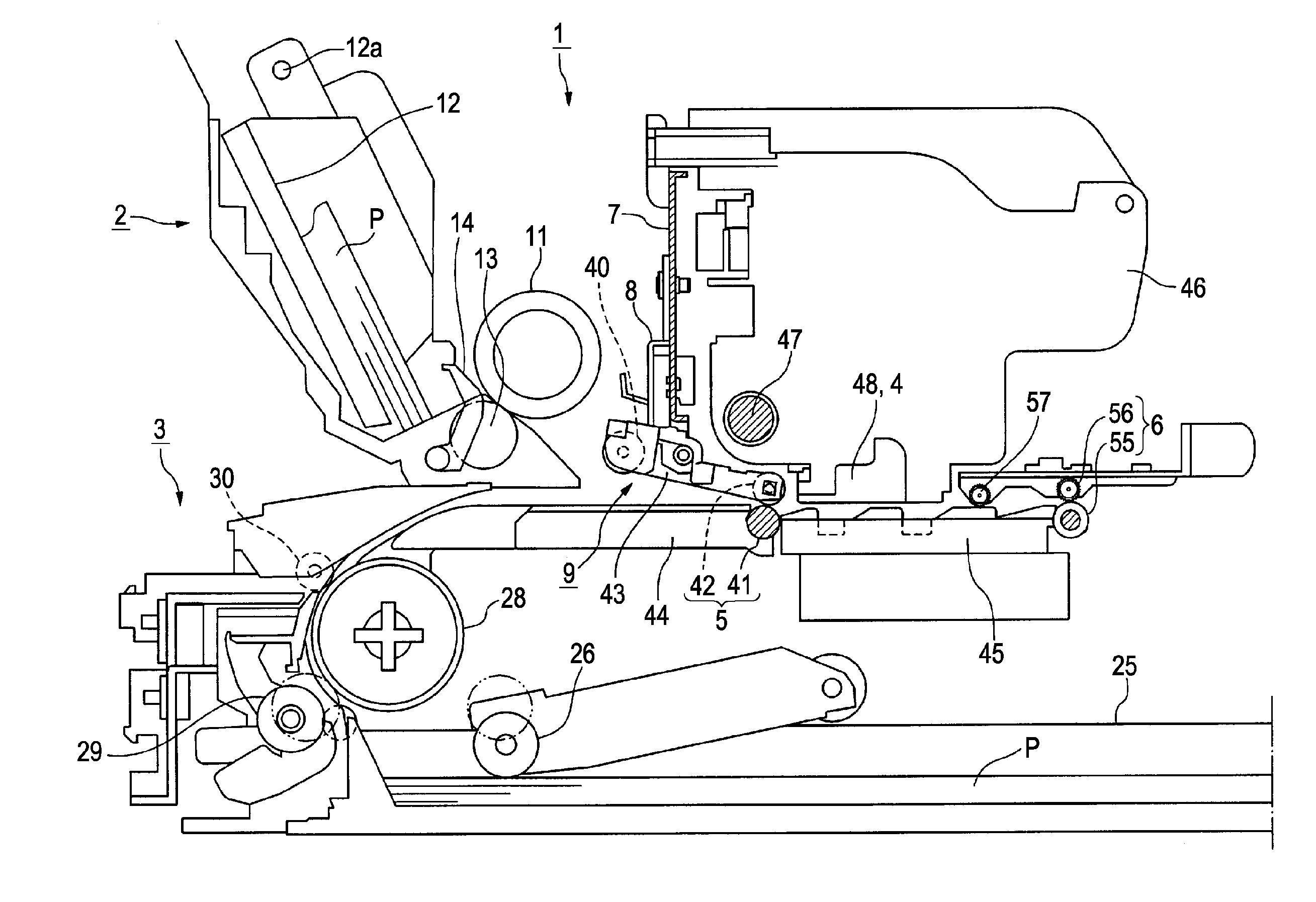
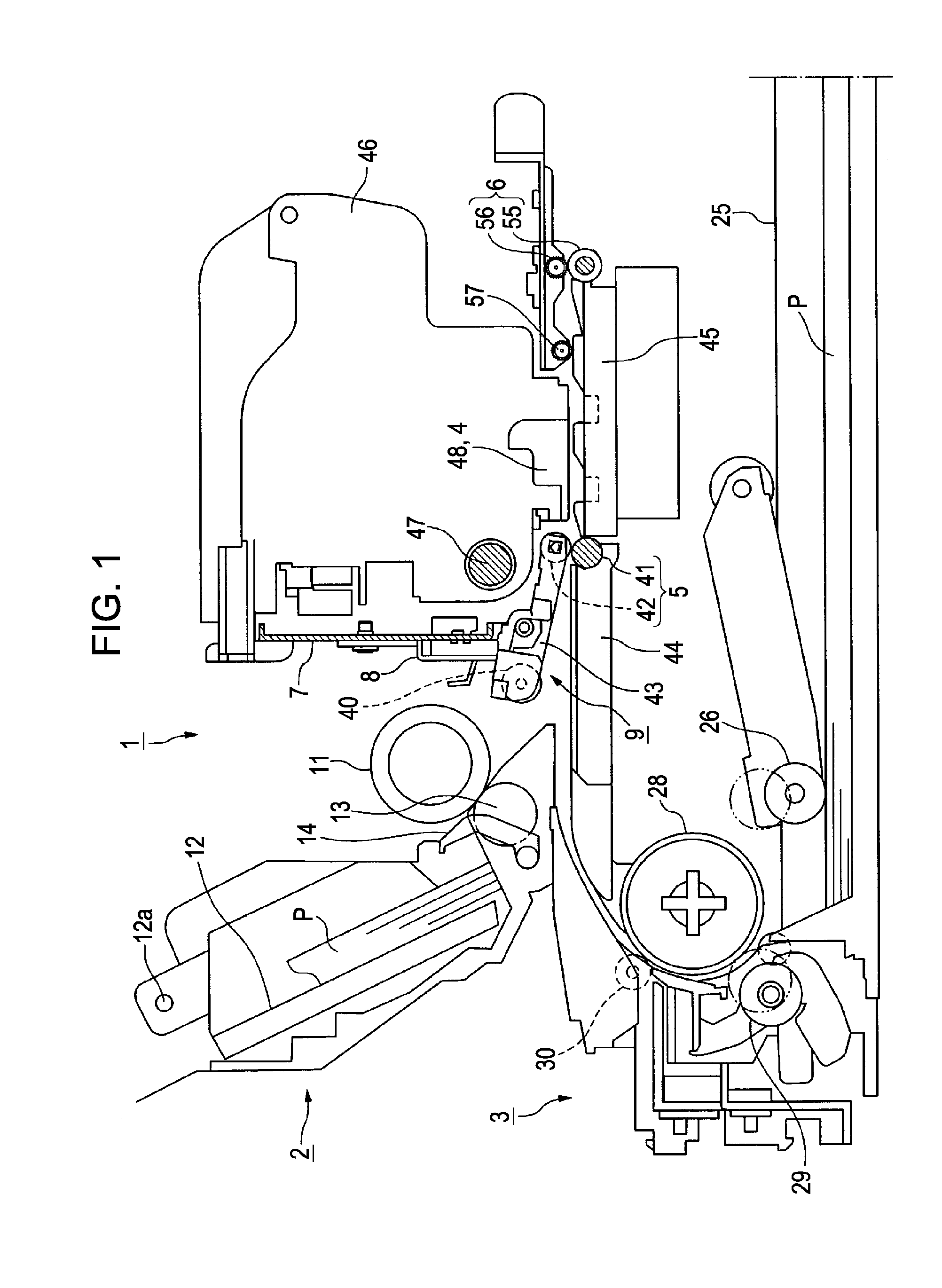
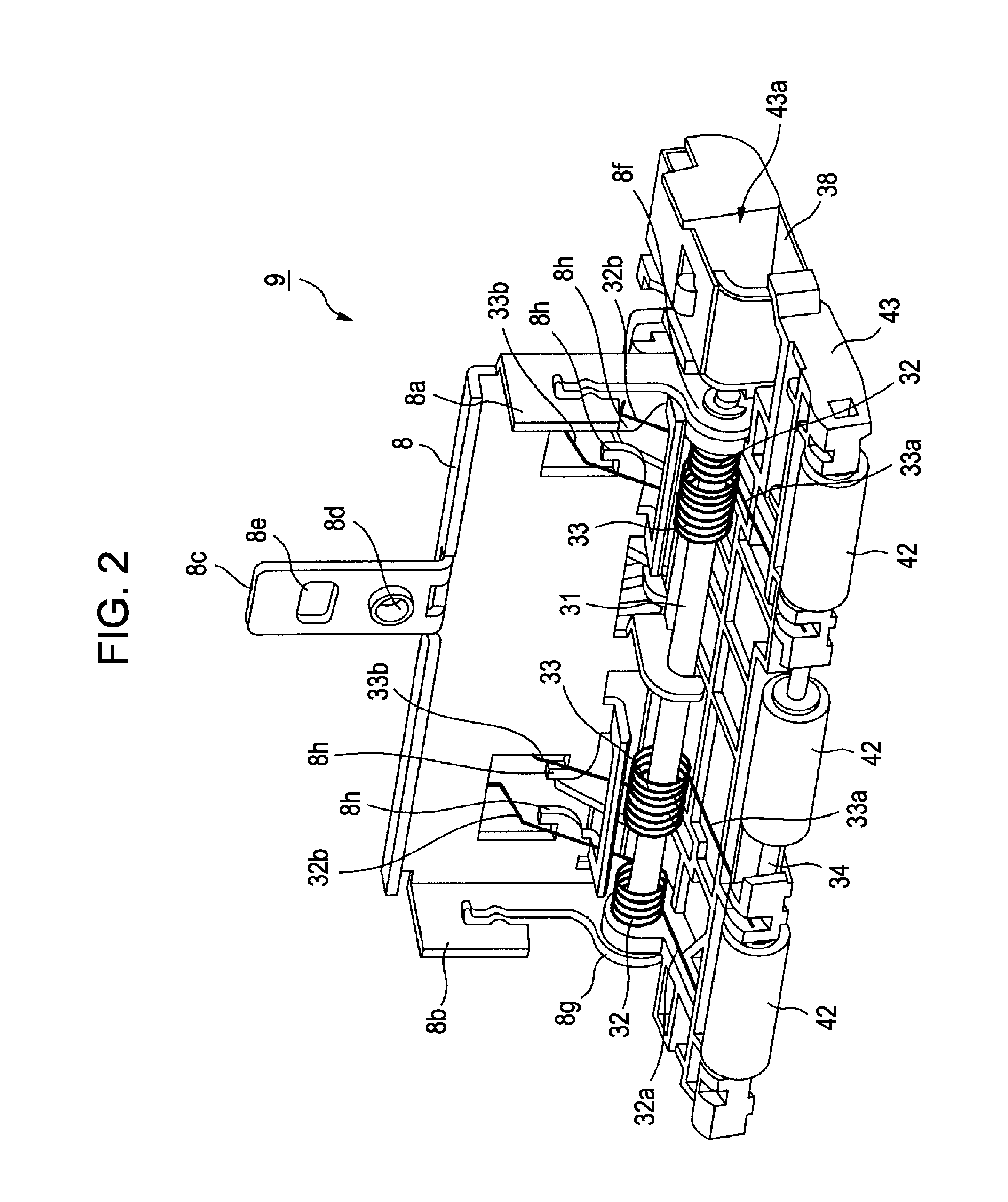
[0031]An embodiment of the invention will now be described with reference to FIGS. 1 to 11C. FIG. 1 is a schematic cross-sectional view of an ink jet printer 1 according to an embodiment of the invention. The ink jet printer 1 corresponds to a recording apparatus or a liquid ejecting apparatus according to the invention, and will simply be referred to as a printer 1 hereinafter. FIG. 2 is a perspective view of an upper sheet-guiding unit 9. FIGS. 3 and 4 are perspective views of the upper sheet-guiding unit 9 in its installed state. Specifically, FIG. 3 is viewed from the front of the printer 1, whereas FIG. 4 is viewed from the back of the printer 1. FIG. 5 is a plan view of the upper sheet-guiding unit 9, as viewed from below. FIG. 6 is a cross-sectional view taken along line VI-VI in FIG. 5. FIG. 7 is a cross-sectional view taken along line VII-VII in FIG. 5. FIG. 8 is a cross-sectional view taken along line VIII-VIII in FIG. 6. FIG. 9 is a perspective view of a rear sheet guide ...


PUM


Abstract

A recording apparatus includes a recording unit that performs recording on a recording medium; a transporting unit disposed upstream of the recording unit and transporting the recording medium downstream; a first guide member and a second guide member disposed facing the first guide member, the first and second guide members having an upstream section of a transport path of the recording medium disposed therebetween; and an optical sensor including a light-emitting portion and a light-receiving portion and having an optical axis that traverses the transport path of the recording medium between the first and second guide members. At least one of the light-emitting portion and the light-receiving portion projects from an outer side of the transport path towards the first guide member. The first guide member has a cutout having an opening that faces the second guide member. The cutout has the light-emitting portion or the light-receiving portion disposed therein. The opening of the cutout is covered with a sheet member except for an area where the optical axis of the optical sensor extends.

Description

BACKGROUND[0001]1. Technical Field[0002]The present invention relates to a recording apparatus equipped with a recording unit that performs recording on a recording medium and a transporting unit that is disposed upstream of the recording unit and transports the recording medium downstream. The invention also relates to a liquid ejecting apparatus.[0003]Here, a liquid ejecting apparatus is not limited to recording apparatuses such as printers, copiers, and facsimile apparatuses that employ an ink jet recording head to perform recording on a recording medium by emitting ink from the recording head. The term “liquid ejecting apparatus” used above is also directed to other apparatuses that allow liquid used for an intended purpose in place of ink to adhere to a liquid-receiving medium, corresponding to a recording medium, by ejecting the liquid from a liquid ejecting head, corresponding to an ink jet recording head, towards the liquid-receiving medium.[0004]In addition to recording hea...

Claims


Application Information

Patent Timeline
IPC IPC(8): G11B7/00
CPCB41J11/0095G03G2215/00721B41J13/103
Inventor KOTAKA, TOSHIKAZUUEYAMA, NAOHIROMOTOHASHI, YASUOWATANABE, SATORU
Owner SEIKO EPSON CORP
Learn More