Electrical safety devices and systems for use with electrical wiring, and methods for using same

a safety device and electrical wiring technology, applied in the direction of electrical equipment, emergency protective circuit arrangements, current measurements only, etc., can solve the problems of 250 deaths, over $670 million of property damage, and many accidents annually, and achieve the effect of rapid detection of wire faults

Inactive Publication Date: 2011-03-17
NEWELL CO INC
View PDF35 Cites 31 Cited by
  • Summary
  • Abstract
  • Description
  • Claims
  • Application Information

AI Technical Summary

Problems solved by technology

Many accidents occur annually due to penetrations of electrical wires or due to deterioration of older wiring systems.
According to reports issued by the Consumer Products Safety Commission (CPSC) in 1997, home wire systems caused over 40,000 fires that resulted in 250 deaths and over $670 million of property damage.
This relatively slow tripping may lead to property damage and / or personal injury.
Circuit breakers do not protect against all hazards that may occur within electrical wiring systems.
For example, circuit breakers are not effective in detecting arc faults.
Any of these situations may be hazardous, so the GFCI trips, breaking the circuit.
However, similar to circuit breakers, a GFCI may be a relatively slow device in order to avoid false tripping.
Additionally, a GFCI is often not effective at detecting certain types of wire faults, such as arc faults.
Additionally, in order to avoid false tripping, an AFCI circuit is typically required to analyze an electrical signature for a relatively long period of time.
These delays may be hazardous, leading to property damage and / or personal injury.
Another problem with many electrical wire safety devices is that they require manual intervention and / or manual reset once a fault is detected.
The electrical wire safety devices are not capable of making a determination of when a fault is no longer present on a monitored wire and, therefore, will maintain the wire in a de-energized state.
This inability to determine when a fault is no longer present can lead to undesirable situations.
For example, an electrical wire that provides power to a refrigerator or freezer may be de-energized by an electrical wire safety device and, if a user does not reset the safety device, perishable food items may spoil.

Method used


Image

  • Electrical safety devices and systems for use with electrical wiring, and methods for using same
  • Electrical safety devices and systems for use with electrical wiring, and methods for using same
  • Electrical safety devices and systems for use with electrical wiring, and methods for using same

Examples


Embodiment Construction

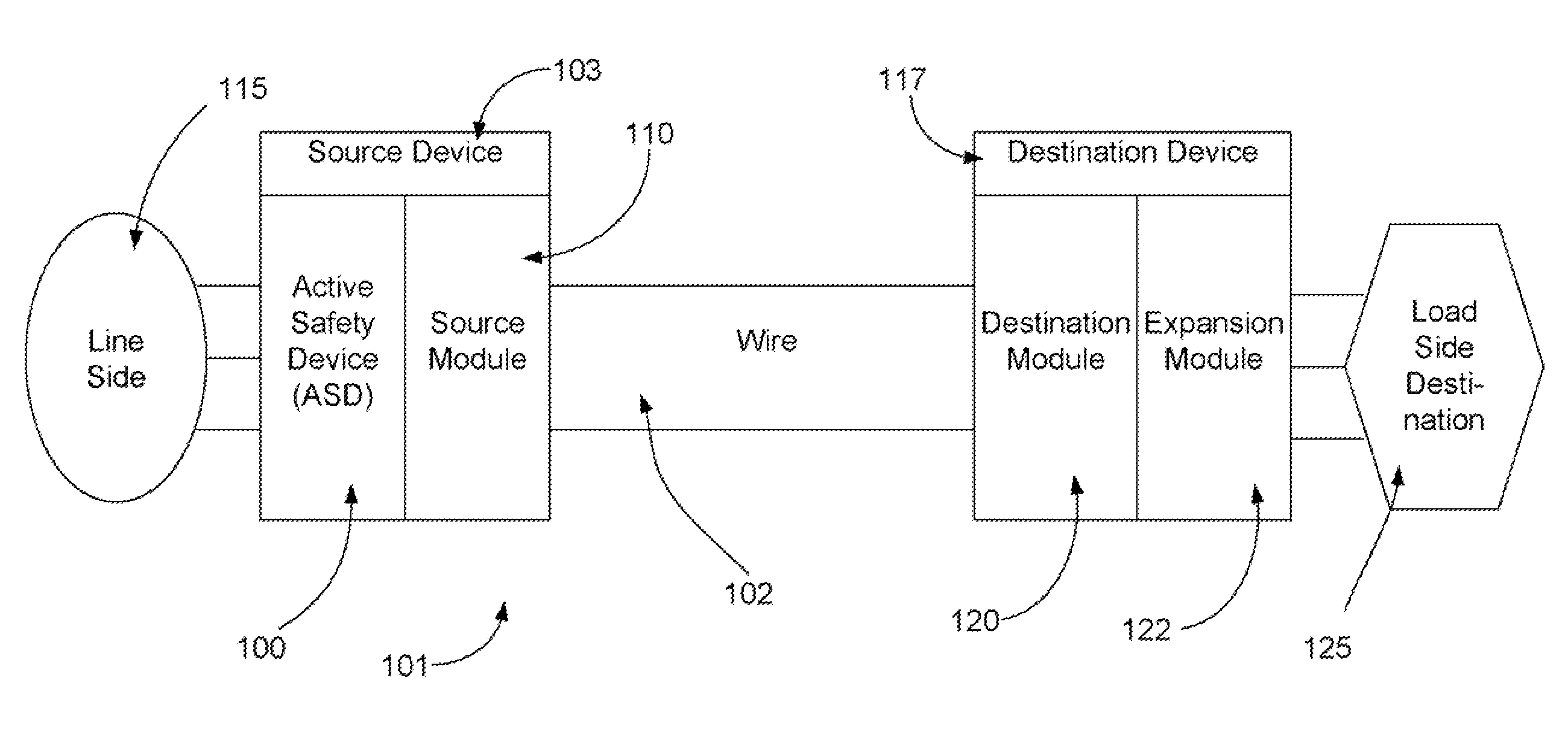
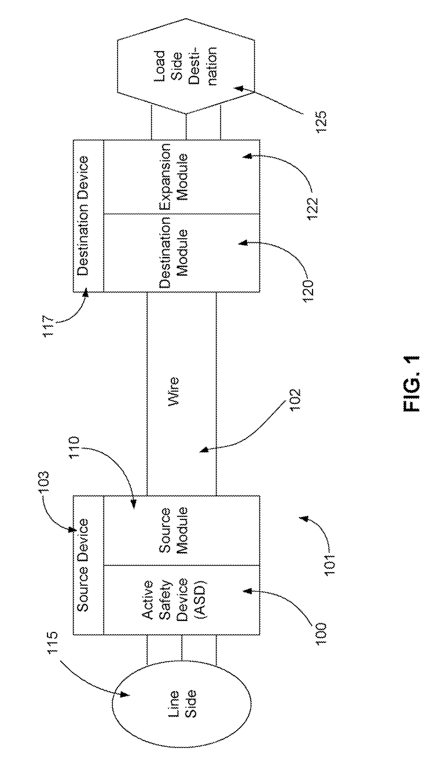
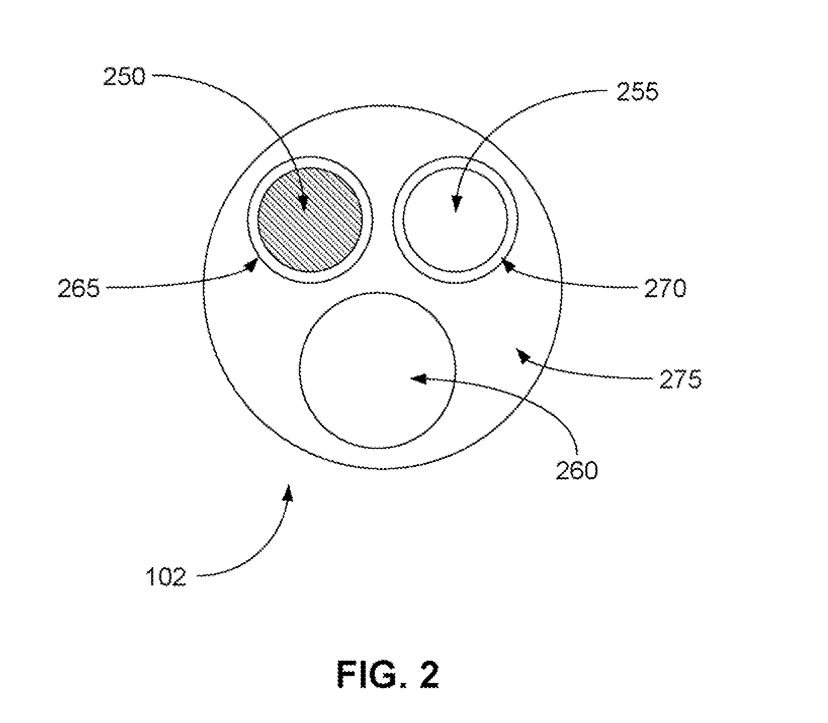
[0032]The invention now will be described more fully hereinafter with reference to the accompanying drawings, in which some, but not all embodiments of the invention are shown. Indeed, embodiments of the invention may be embodied in many different forms and should not be construed as limited to the embodiments set forth herein: rather, these embodiments are provided so that this disclosure will satisfy applicable legal requirements. Like numbers refer to like elements throughout.

[0033]As used herein, the term “relay” may refer to any suitable device, component, system, and / or combination thereof that facilitates the electrification of a wire and / or control over the electrification of a wire. Examples of relays include, but are not limited to, electrical switches, mechanical switches, electromechanical switches, electromagnetic switches, triacs, and / or any other suitable disconnection component. Additionally, for purposes of this disclosure, the terms “relay” and “disconnection compo...


PUM


Abstract

Disclosed are systems and methods for monitoring an electrical wire. A safety device utilized to monitor the wire may include at least one current sensing device, at least one voltage sensing device, and at least one processing component. The current sensing device measures a current on at least one conductor of the wire. The voltage sensing device measures a voltage associated with the safety device. The at least one processing component receives the measurements and identifies, based upon the current measurement, an overcurrent event. The processing component then compares the voltage measurement to a stored voltage value and determines, based upon the comparison, that a difference between the voltage measurement and the stored voltage value satisfies a threshold condition. The processing component directs, based upon the determination, at least one relay to be opened to discontinue provision of an electrical power signal onto the electrical wire.

Description

CROSS REFERENCE TO RELATED APPLICATIONS[0001]This application is a continuation-in-part of co-pending U.S. patent application Ser. No. 12 / 398,660, filed Mar. 5, 2009, entitled ELECTRICAL SAFETY DEVICES AND SYSTEMS FOR USE WITH ELECTRICAL WIRE, AND METHODS FOR USING SAME, which is a continuation-in part of co-pending U.S. patent application Ser. No. 11 / 782,450, filed Jul. 24, 2007, entitled ELECTRICAL SAFETY DEVICES AND SYSTEMS FOR USE WITH ELECTRICAL WIRING, AND METHODS FOR USING SAME, which claims priority to U.S. Provisional Application No. 60 / 820,197, entitled ACTIVE SAFETY DEVICES, which was filed on Jul. 24, 2006. Additionally, U.S. patent application Ser. No. 12 / 398,660 claims priority to U.S. Provisional Application No. 61 / 034,002, filed Mar. 5, 2008, entitled ACTIVE SAFETY DEVICES AND METHODS FOR USE WITH ELECTRICAL WIRE. The disclosures for each or these applications are incorporated herein by reference in their entirety.FIELD OF THE INVENTION[0002]Embodiments of the invent...

Claims


Application Information

Patent Timeline
Patent Type & Authority Applications(United States)
IPC IPC(8): H02H3/00
CPCG01R19/0092H02H7/228H02H3/38H02H3/10
Inventor SEXTON, ROBERT JAYMARTIN, FRED LANE
Owner NEWELL CO INC
Why Eureka
Try Eureka