Isolator decoupler

Active Publication Date: 2011-03-17
THE GATES CORP
View PDF12 Cites 116 Cited by
  • Summary
  • Abstract
  • Description
  • Claims
  • Application Information

AI Technical Summary

Problems solved by technology

Under this circumstance, the tensioner cannot accommodate all of the variable torque characteristics and belt load cha

Method used


Image

  • Isolator decoupler
  • Isolator decoupler
  • Isolator decoupler

Examples


Embodiment Construction

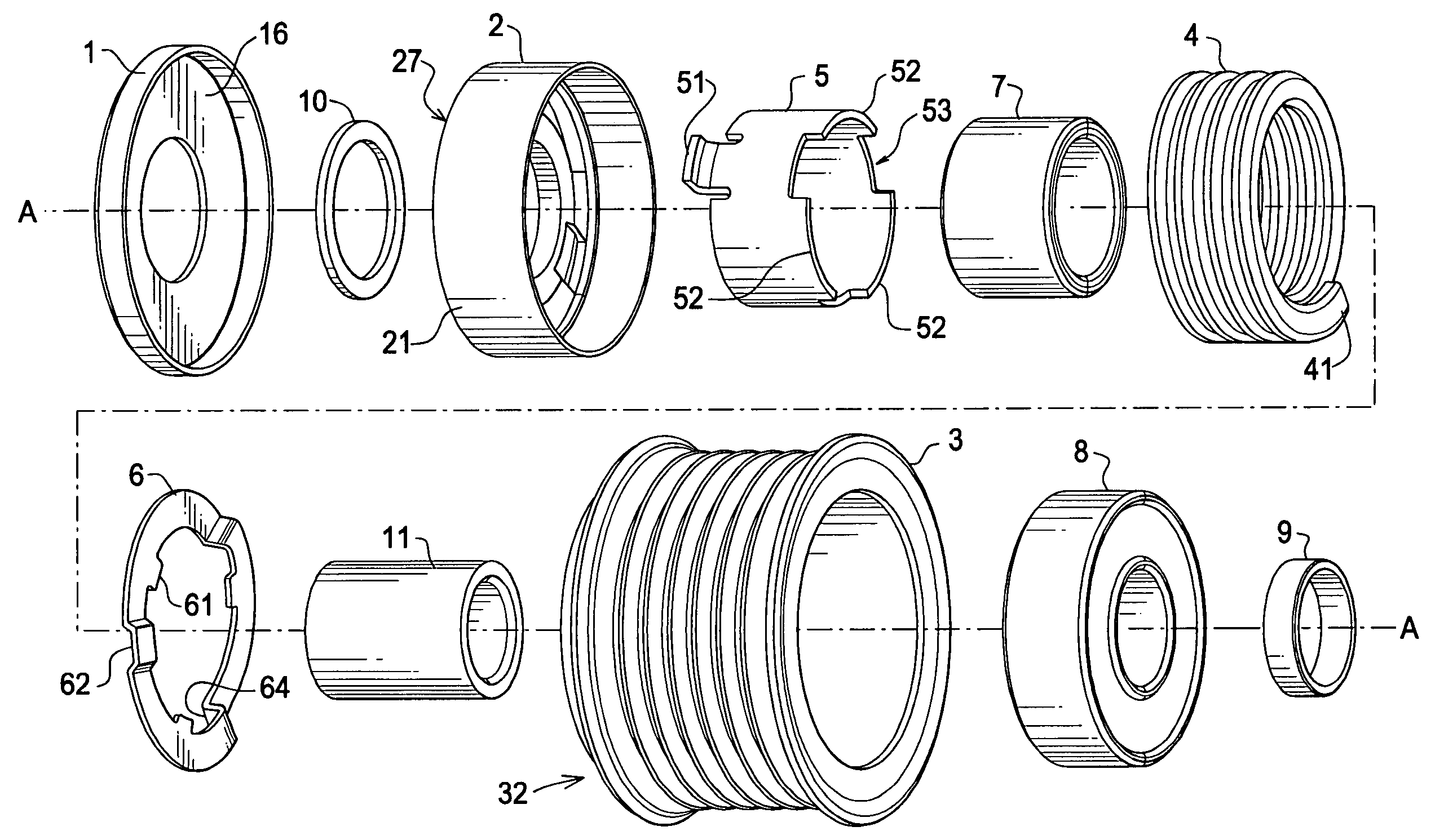
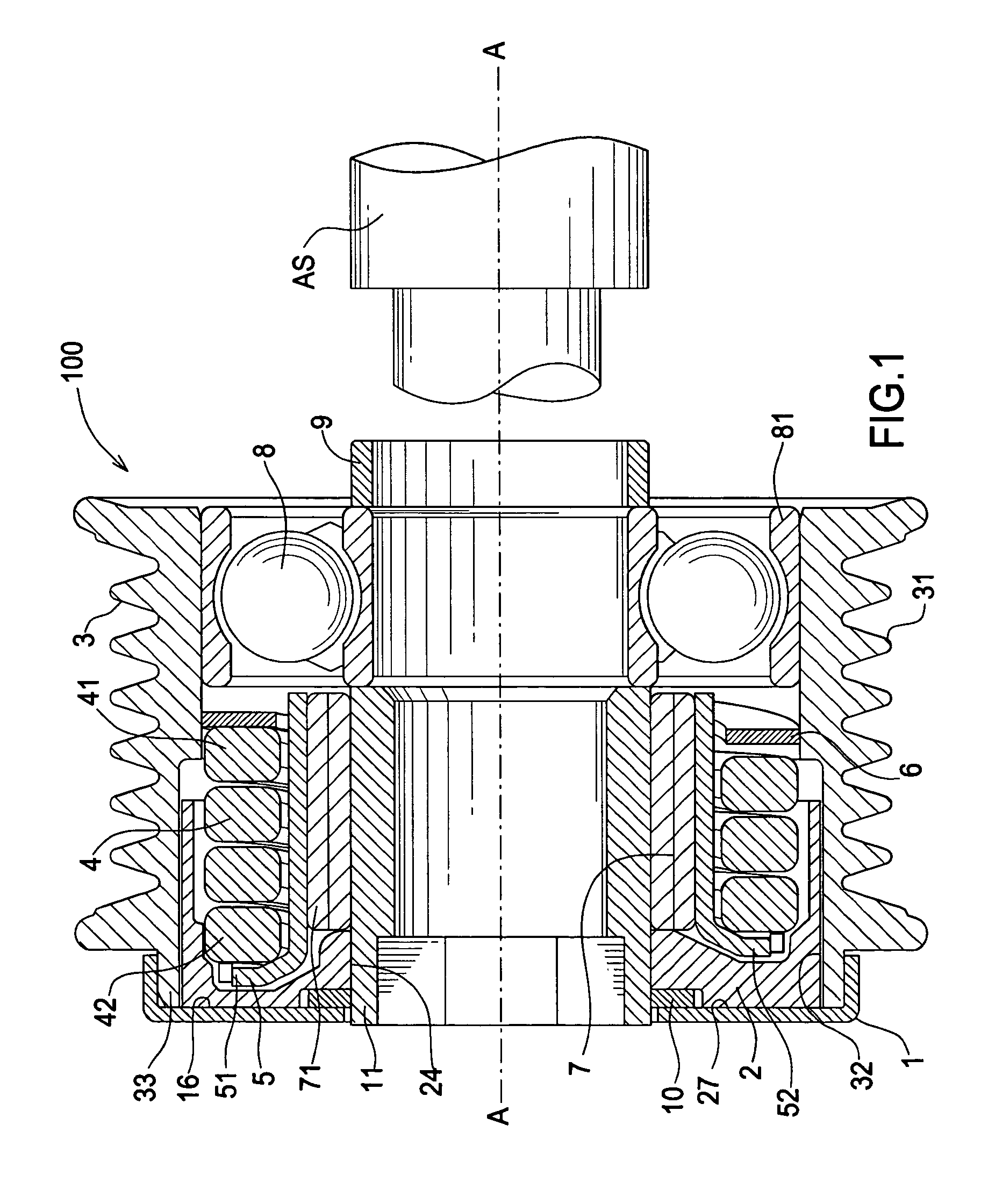
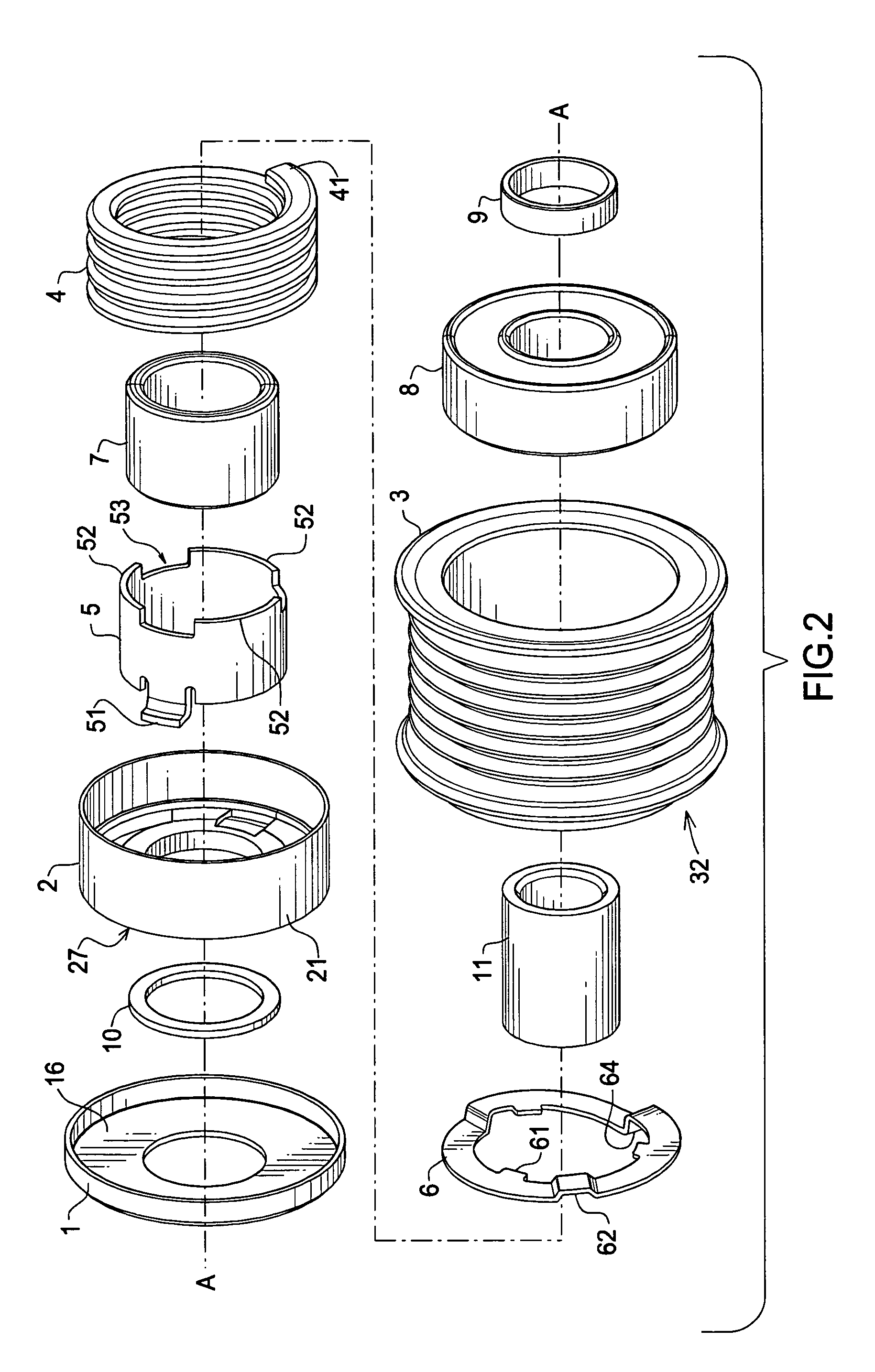
FIG. 1 is a cross sectional view of the isolator decoupler. Isolator decoupler 100 comprises a pulley 3 having a multi-ribbed surface 31. Pulley 3 is rotationally mounted to the outer race 81 of a ball bearing 8. Bearing 8 may also comprise a sleeve, bushing, needle or other suitable form of bearing.

A spring retainer 6 is press fit into the pulley 3. An end 41 of torsion spring 4 engages spring retainer 6. The other end 42 of torsion spring 4 engages plastic bushing 2. Bushing 2 is disposed between pulley 3 and shaft 11.

One-way clutch 7 is a roller type clutch having a cage and an inner and outer race. The inner diameter of the one-way clutch is formed by the shaft 11. A clutch carrier 5 is press fit onto the one-way clutch outer race 71.

Clutch carrier 5 comprises two tabs 51 that extend radially from the carrier in a direction normal to an axis of rotation A-A. Each tab 51 cooperatively engages a recess 22 in bushing 2, whereby torque is transmitted. Engaging tabs 51 into recesses ...


PUM


Abstract

An isolator decoupler comprising a pulley, a shaft, a bushing slidingly engaged with the pulley and slidingly engaged with the shaft, the pulley journalled to the shaft by a bearing, a one-way clutch fixed to the shaft and engaged with the bushing whereby the bushing rotates in unison with the one-way clutch, a torsion spring engaged between the pulley and the one-way clutch to resiliently couple the pulley to the shaft, and the pulley non-resiliently directly coupleable to the shaft in a temporary predetermined loaded condition.

Description

FIELD OF THE INVENTIONThe invention relates to an isolator decoupler, and more particularly, to an isolator decoupler wherein a torsion spring engaged between the pulley and the one-way clutch to resiliently couple the pulley to the shaft, and the pulley non-resiliently directly coupleable to the shaft in a temporary predetermined loaded condition.BACKGROUND OF THE INVENTIONSerpentine accessory drive systems are routinely used in automotive vehicles to drive engine accessories. A typical serpentine drive system includes a driving pulley on the crankshaft of an internal combustion engine of the vehicle, a series of driven pulleys for the accessories and a multi-ribbed belt trained about the driving and driven pulleys. An advantage of the serpentine drive is that, by providing an automatic belt tensioner on the belt, the accessories can be fixedly mounted.The driving pulley establishes a highly dynamic loading on the belt. This high dynamic loading is due to the variable torque output...

Claims


Application Information

Patent Timeline
IPC IPC(8): F16H55/36
CPCF16D7/022F16D41/206F16H2055/366F16H55/36F16F15/1216F16D41/20F16D7/02
Inventor SERKH, ALEXANDERALI, IMTIAZWARD, PETER
Owner THE GATES CORP
Why Eureka
Try Eureka