Input method and input device of portable terminal

a portable terminal and input method technology, applied in the field of portable terminals, can solve the problems of not allowing the user to generate a sophisticated touch event, portable terminal cannot generate a variety of input signals,

Inactive Publication Date: 2011-03-24
SAMSUNG ELECTRONICS CO LTD
View PDF13 Cites 87 Cited by
  • Summary
  • Abstract
  • Description
  • Claims
  • Application Information

AI Technical Summary

Benefits of technology

[0008]In accordance with an exemplary embodiment of the present invention, the present invention provides an input device of a portable terminal including: a sensing unit, a controller, and a storage unit. The sensing unit detects a pressure value corresponding to a mechanical force applied to the portable terminal. The controller determines whether the pressure value is equal to or less than a preset value. The controller ascertains that a current state is a grip state if the pressure value is equal to or less than the preset value and that the current state is a squeeze state if the pressure value is greater than the preset value. The controller generates commands according to the grip state and the squeeze state and applies the generated commands to a currently enabled application program. The storage unit stores the application program.
[0009]In accordance with another exemplary embodiment of the present invention, the present invention provides an input method of a portable terminal including: detecting a pressure value corresponding to a mechanical force applied to the portable terminal; determining whether the pressure value is equal to

Problems solved by technology

However, conventional portable terminals are disadvantageous in that they allow the user to use a touch screen function in a state where the display unit is enabled.
In addition, conventional portable terminals have also drawbacks in that their touch panel does not allow the user to generate a sophisticated touch ev

Method used


Image

  • Input method and input device of portable terminal
  • Input method and input device of portable terminal
  • Input method and input device of portable terminal

Examples


first embodiment

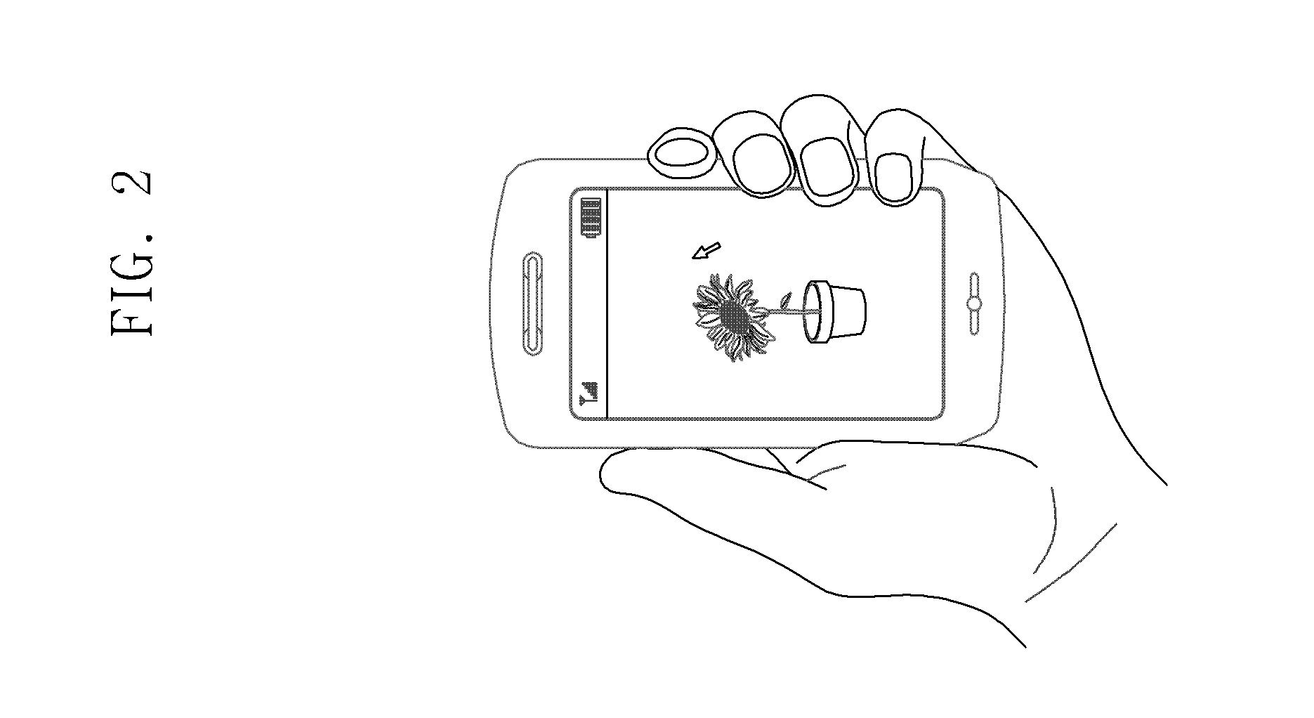
[0049]FIG. 4 shows screen views that describe the operation of the portable terminal according to the present invention.

[0050]Referring to FIGS. 1 to 4, when a user grasps the portable terminal 100, increases a force applied to the sensing unit 170 installed to the side of the portable terminal 100, an image displayed on the display panel 141 is changed in size. More specifically, if the user applies a gripping force to the sensing unit 170 and the sensing unit 170 detects a force with a range, equal to or greater than 1 N but less than 2 N, the portable terminal 100 displays an image of a certain size on the display panel 141 as shown in diagram 401 of FIG. 4. After that, if the user applies a gripping force greater than a previous gripping force to the sensing unit 170 and the sensing unit 170 then detects a force in a range equal to or greater than 2 N but less than 3 N, the portable terminal 100 displays an image, larger than the image shown in diagram 401, on the display panel ...

second embodiment

[0052]FIG. 5 shows screen views that describe the operation of the portable terminal according to the present invention. It is assumed that the portable terminal user initially continues applying a force equal to or greater than 4 N to the sensing unit 170.

[0053]Referring to FIGS. 1 to 5, when a user grasps the portable terminal 100 and applies a force equal to or greater than 4 N to the sensing unit 170 installed to the side of the portable terminal 100, a zoomed-in image is displayed on the display panel 141. If the user reduces the force applied to the sensing unit 170, the image is correspondingly zoomed out and displayed on the display panel 141. More specifically, if the user applies a force to the sensing unit 170 and the sensing unit 170 then detects a force equal to or greater than 4 N, the portable terminal 100 displays an image of a certain size on the display panel 141 as shown in diagram 501 of FIG. 5. After that, if the user applies a smaller force than the previous fo...

third embodiment

[0055]FIG. 6 shows screen views that describe the operation of the portable terminal according to the present invention.

[0056]Referring to FIGS. 1 to 6, when the user grasps the portable terminal 100 and enables a menu function, the portable terminal 100 displays a menu screen on the display panel 141 as shown in diagram 601. More specifically, if the user holds the sensing unit 170 installed to the external body of the portable terminal 100 with a pressure value equal to or less than a certain value, the portable terminal 100 can detect a grip state. In that case, the sensing unit 170 generates a grip-state sensing signal and outputs it to the controller 160. The controller 160 generates a command for conducting a particular function based on the grip-state sensing signal. For example, the controller 160 can generate a command for displaying a menu screen according to the setting of the portable terminal 100 and display a menu screen based on the command. The controller 160 can als...


PUM


Abstract

An input method and device of a portable terminal is disclosed. If the pressure value corresponding to a mechanical force applied to the external body of the portable terminal is equal to or less than a preset value, the portable terminal ascertains that the current state is a grip state. If the pressure value is greater than the preset value, the portable terminal ascertains that a current state is a squeeze state. The command generated according to the grip state and the squeeze state is applied to a currently enabled application program.

Description

CLAIM OF PRIORITY[0001]This application claims, pursuant to 35 USC 119, priority to and the benefit of the earlier filing date of, that patent application filed in the Korean Patent Office, entitled “Input Method and Input Device of Portable Terminal,” on Sep. 21, 2009 and afforded serial no. 10-2009-0089202, the entire contents of which are incorporated by reference, herein.BACKGROUND OF THE INVENTION[0002]1. Field of the Invention[0003]The present invention relates to portable terminals, and more particularly, to an input method and input device that generates a input signal according to pressure applied the portable terminal and a variety of input signals associated with other input systems.[0004]2.Description of the Related Art[0005]Portable terminals have been widely used because of their convenience in their functionality and their ability to be easily carried. Portable terminals employ a variety of input methods to provide user functions. For example, the terminals may be equ...

Claims


Application Information

Patent Timeline
IPC IPC(8): G06F3/041G05B23/02G09G5/00G10L11/00G06F3/048
CPCG06F3/01G10L15/26G06F3/048G06F3/0487G06F1/1626G06F1/1684
Inventor KIM, JIN YONG
Owner SAMSUNG ELECTRONICS CO LTD
Why Eureka
Try Eureka