AI technical title is built by Patsnap AI team. It summarizes the technical point description of the patent document.
a scatter detection and x-ray technology, applied in the field of inspection systems, can solve the problems of inability to detect scatter, and inability to use detectors in applications requiring distances greater than five feet, so as to prevent damage to detectors and minimize bounce
Inactive Publication Date: 2011-03-31
AMERICAN SCI & ENG INC
View PDF71 Cites 30 Cited by
Summary
Abstract
Description
Claims
Application Information
AI Technical Summary
This helps you quickly interpret patents by identifying the three key elements:
Problems solved by technology
Method used
Benefits of technology
Benefits of technology
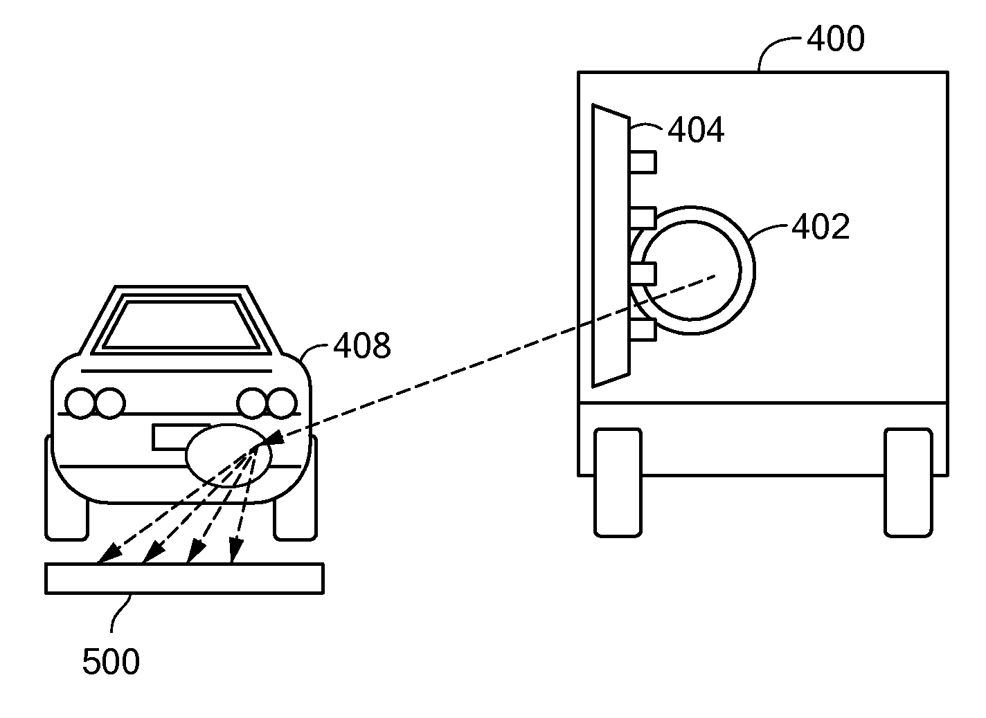
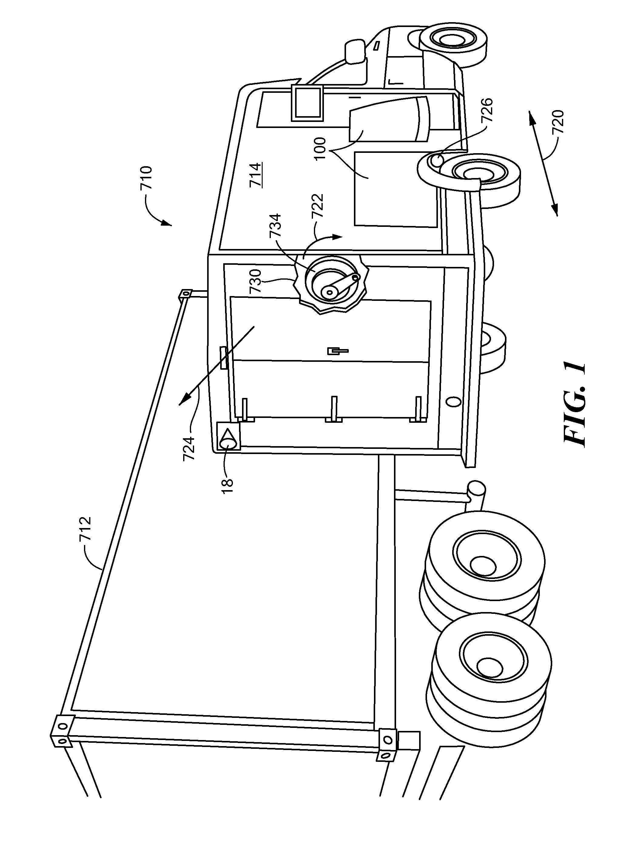
[0019]In accordance with further embodiments of the present invention, the source of penetrating radiation, the detector, or both may be located on one or more vehicles, including robotic drone vehicles, capable of road travel. The source of penetrating radiation may be mounted on a swivel mount to allow the beam to be directed at objects in various locations. The inspection system may further include a stabilization system to minimize bounce when the vehicle is traversing rough terrain.
[0020]In yet further embodiments of the present invention, the detectors may be located in the ground or ceiling of a passageway and may be camouflaged. Detectors located in the ground may further include structural supports to prevent damage to the detector when objects pass over, and pressure sensors to detect the presence of an object.
Problems solved by technology
One such application is where personnel to be inspected might be carrying explosive devices carried under clothing or concealed in backpacks or bags and the risk of suicide detonation is present.
Current x-ray inspection systems are often inadequate in such applications and are rarely used in applications requiring distances greater than five feet.
However, if the distances are too great, the detectors required will be impractically large.
Additionally, as the flux increases, so will the objects exposure, which poses a problem when the object is, or may contain, a person.
One consideration, however, is that metal objects (such as artillery shells) within a metallic container (such as a vehicle) may not be well-detected unless favorably silhouetted against a brightly scattering background of organic material.
Another issue for backscatter technology is that it can sometimes be difficult to image organic materials when they are placed within or behind significant amounts of high-Z material, such as steel.
This problem is often exacerbated because the scattered x-rays reach backscatter detectors having passed through an intervening steel surface at an oblique angle, resulting in an effective thickness of steel that is greater than the actual gauge of the steel.
Method used
Image
Click on the blue label to locate the original text in one second.
Reading with bidirectional positioning of images and text.
Examples
Embodiment Construction
[0011]Representative embodiments of the present invention include a system and a method for inspecting an object. The object is illuminated with a collimated beam of penetrating radiation. Backscattered radiation from the beam is detected. Characteristic values of the backscattered radiation are compared to expected reference values. Based on the comparing, a descriptive category is determined which characterizes the object.
[0012]In further embodiments, the penetrating radiation may be x-ray radiation. The descriptive category may, for example, indicate abnormally high metallic content when the characteristic values are less than the expected reference values, or abnormally high organic content when the characteristic values are greater than the expected reference values. The descriptive category may indicate a potential or confirmed security threat according to pre-established security threat criteria.
[0013]In some embodiments, the method may further include selecting the object fo...
PUM
Property
Measurement
Unit
distances
aaaaa
aaaaa
average energy
aaaaa
aaaaa
dynamic aspect ratio
aaaaa
aaaaa
Abstract
Systems and methods for inspecting an object with a scanned beam of penetrating radiation. Scattered radiation from the beam is detected, in either a backward or forward direction. Characteristic values of the scattered radiation are compared to expected reference values to characterize the object. Additionally, penetrating radiation transmitted through the inspected object may be combined with scatter information. In certain embodiments, the inspected field of view is less than 0.1 steradians, and the detector is separate from the source of penetrating radiation and is disposed, with respect to the object, such as to subtend greater than 0.5 steradians in the field of view of the object.
Description
[0001]The present application is a divisional application of copending U.S. Ser. No. 12 / 368,736, a continuation-in-part application of copending U.S. Ser. No. 11 / 608,957, filed Dec. 11, 2006, now issued as U.S. Pat. No. 7,505,556, itself a continuation-in-part application of U.S. Ser. No. 11 / 238,719, filed Sep. 29, 2005, now issued as U.S. Pat. No. 7,218,704, which is a continuation application of U.S. Ser. No. 10 / 442,687, filed May 21, 2003, now issued as U.S. Pat. No. 7,099,434, which was a continuation-in-part of U.S. Ser. No. 10 / 330,000, filed Dec. 26, 2002, and claimed priority from U.S. Provisional Application Ser. No. 60 / 424,357, filed Nov. 6, 2002, as does the present application. All of the foregoing applications are incorporated herein by reference.[0002]U.S. Ser. No. 12 / 368,736, of which the present application is a divisional, is also a continuation-in-part of U.S. Ser. No. 11 / 551,991, filed Oct. 23, 2006, and issued as U.S. Pat. No. 7,551,715, and claims priority, throu...
Claims
Application Information
Patent Timeline
Application Date:The date an application was filed.
Publication Date:The date a patent or application was officially published.
First Publication Date:The earliest publication date of a patent with the same application number.
Issue Date:Publication date of the patent grant document.
PCT Entry Date:The Entry date of PCT National Phase.
Estimated Expiry Date:The statutory expiry date of a patent right according to the Patent Law, and it is the longest term of protection that the patent right can achieve without the termination of the patent right due to other reasons(Term extension factor has been taken into account ).
Invalid Date:Actual expiry date is based on effective date or publication date of legal transaction data of invalid patent.
Patent Type & AuthorityApplications(United States)

