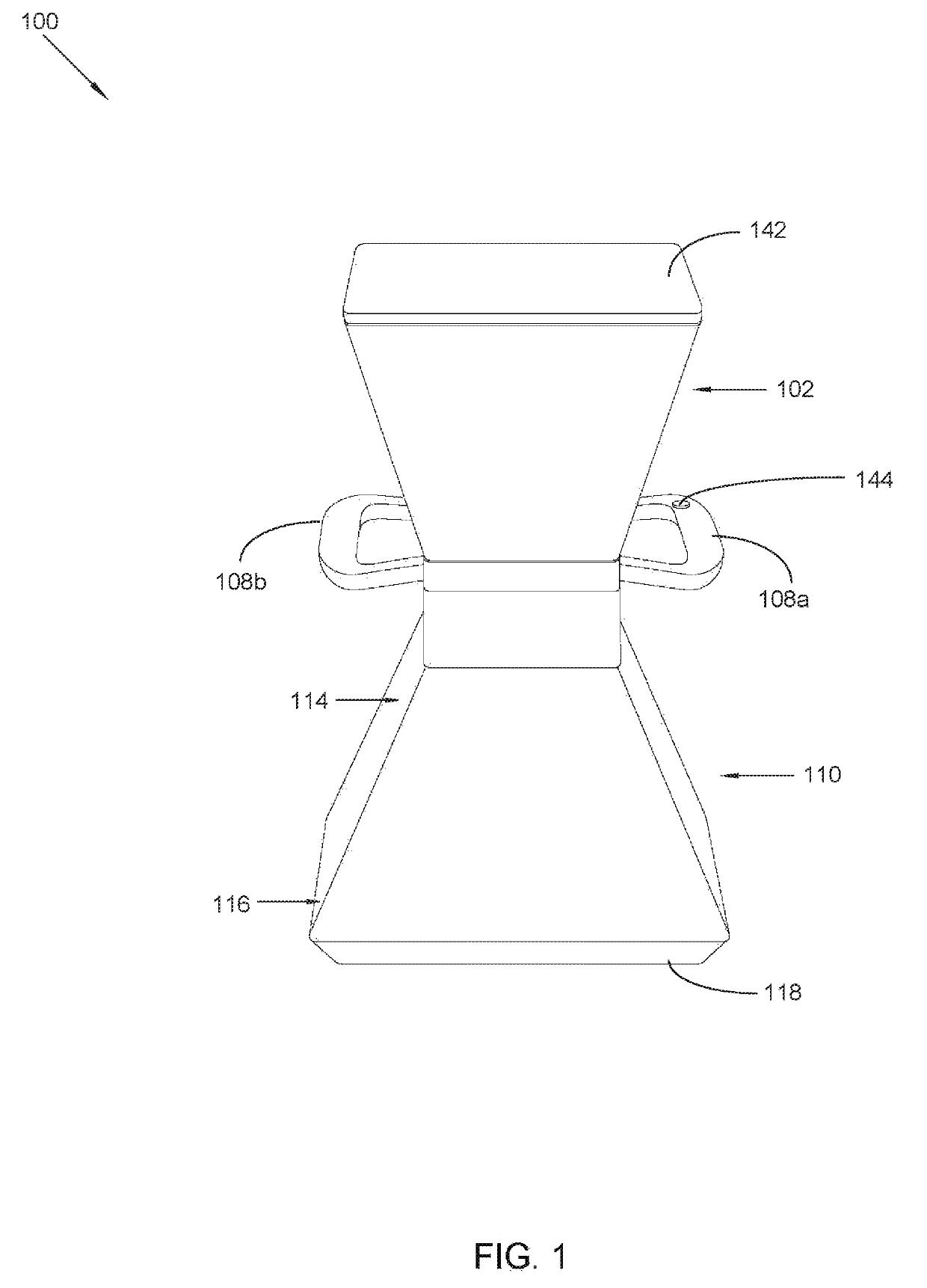
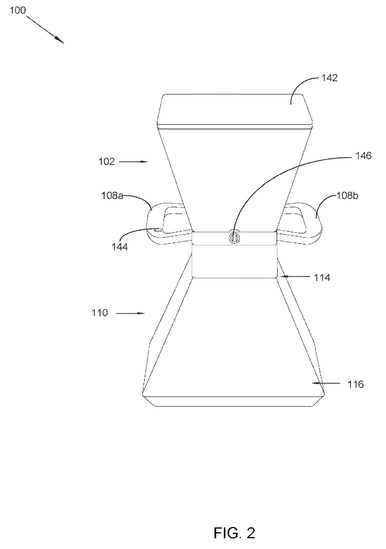
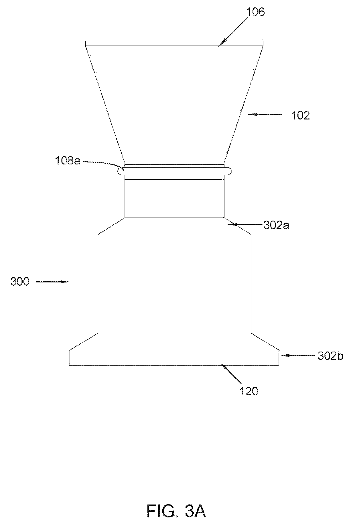
Electric handheld broadcast spreader with pattern and speed controlling baffled skirt

a technology of broadcast spreader and pattern, which is applied in the direction of centrifugal wheel fertiliser, way, construction, etc., can solve the problems of difficult or impossible use on uneven surfaces, difficult or impossible storage, and difficult or impossible to store on uneven surfaces, etc., and achieves the effect of rapid spread of ice mel

Inactive Publication Date: 2019-08-13
BEHR LAURENCE D
View PDF8 Cites 0 Cited by
  • Summary
  • Abstract
  • Description
  • Claims
  • Application Information

AI Technical Summary

Benefits of technology

[0015]This, in turn, causes the particulate material to disperse within a proximal coverage area of a ground surface, such as within the boundaries of a sidewalk, and away from the feet of the operator. This velocity and directional control also minimizes bouncing of particulate material on the ground surface. Further, the system allows the coverage area of particulate material across the ground surface to be increased or decreased by raising and lowering the apparatus. Further, the discharge velocity of the particulate material is controlled through a velocity switch.
[0051]Further, unlike most existing handheld spreaders, this invention shields the feet of the user from its broadcast while also ensuring that the user walks forward safely upon a dangerous surface, i.e., slick ice, that has been amply treated directly in front of him or her.

Problems solved by technology

Drawbacks of both types of walk-behind spreaders include that they are often heavy and / or cumbersome, and are hard to store; are often subject to mechanical wear and malfunction are difficult or impossible to use on uneven surfaces and in tight or confined areas; and, are useless for treating ice on stairs, steps and door stoops.
The broadcast variety is unusable to de-ice sidewalks and paths because the product would be flung also onto lawns, causing damage, or into streets, causing waste.
The uncontrolled pattern of the broadcast spreaders makes it hard to fertilize and “weed control” lawns without either excessive or inadequate overlap of multiple “passes,” or possibly casting product where it may cause harm (e.g., flowerbeds).
Drop spreaders are commonly used to de-ice sidewalks and paths because they closely confine the pattern of dispersal to the width of the device, but in use such machines often prove to be rife with mechanical and functional issues.
In addition on icy sidewalks or paths their wheels may not have sufficient traction to drive the dispersing mechanism.
Presently available handheld broadcast spreaders, both electric and hand-cranked, like walk-behind broadcast spreaders, are useless for icy sidewalks and paths because they overspray onto lawns and into streets, etc.
Both varieties of broadcast spreaders, handheld and walk-behind, have also the above-noted drawbacks when used for fertilizing and weed control products: the difficulties of achieving even and uniform distribution, and avoiding overspray onto undesirable surfaces.
For ice treatment on sidewalks, paths and driveways many homeowners use shaker bottles, which, although cheap and convenient, can easily produce very uneven results.
Further, unlike this invention, which drops pellets and rock salt in a gentle shower within a tightly controlled pattern (if desired), existing handheld spreaders fail to reduce the velocity and force with which hard, pelletized substances, such as rock salt and calcium chloride, strike hard surfaces such as ice, concrete and asphalt, with the resulting bounce and travel making the spread of such substance onto lawns, etc., uncontrollable.
Further, unlike this invention, existing handheld spreaders are not held by both hands, and thus do not allow the user, (A), to easily raise and lower the spreader so as to adjust the scope of the broadcast; nor (B), to control both rate of flow, and operation of the motor, without moving either of his or her hands.

Method used


Image

  • Electric handheld broadcast spreader with pattern and speed controlling baffled skirt
  • Electric handheld broadcast spreader with pattern and speed controlling baffled skirt
  • Electric handheld broadcast spreader with pattern and speed controlling baffled skirt

Examples


Embodiment Construction

[0064]The following detailed description is merely exemplary in nature and is not intended to limit the described embodiments or the application and uses of the described embodiments. As used herein, the word “exemplary” or “illustrative” means “serving as an example, instance, or illustration.” Any implementation described herein as “exemplary” or “illustrative” is not necessarily to be construed as preferred or advantageous over other implementations. All of the implementations described below are exemplary implementations provided to enable persons skilled in the art to make or use the embodiments of the disclosure and are not intended to limit the scope of the disclosure, which is defined by the claims. For purposes of description herein, the terms “upper,”“lower,”“left,”“rear,”“right,”“front,”“vertical,”“horizontal,” and derivatives thereof shall relate to the invention as oriented in FIG. 1. Furthermore, there is no intention to be bound by any expressed or implied theory pres...


PUM


Abstract

An electric handheld broadcast spreader with pattern and speed controlling baffled skirt detachably attaches to a conventional spreader mechanism to disperse particles in a controlled, directional manner within a proximal coverage area with two hands. A broadcasting / dispersing skirt receives particulate material from a conventional spreader. The inner volume of broadcasting / dispersing skirt comprises upper layer baffles, with upper gaps forming between each upper layer baffle; lower layer baffles, offset from the upper layer baffles, with lower gaps forming between each lower layer baffle; and multiple vertical deflector vanes disposed perpendicular to lower layer baffles. Discharged particulate material strikes the surface of the baffles, before passing through gaps. The particulate material traveling in a lateral direction strikes the deflector vanes and outlet edge of broadcasting / dispersing skirt. This controls velocity and direction of dispersed particulate material, causing particulate material to be confined within a close pattern coverage area on ground surface.

Description

FIELD OF THE INVENTION[0001]The present invention relates generally to an electric handheld broadcast spreader with pattern and speed controlling baffled skirt. More so, the present invention relates to a particulate material broadcasting skirt and baffle system that detachably attaches to a motorized broadcasting mechanism to slow the speed of particulate material and eject the particulates in a controlled manner within a close, proximal coverage area while being manipulated with two hands; whereby the system includes a particulate material storage hopper attached to an electric motor-driven conventional spreader that forcibly discharges particulate material, and a diffuser skirt that receives the particulate material for broadcasting in a close pattern coverage area on the ground surface; whereby the inner volume of the diffuser skirt comprises multiple upper layer baffles traversing an upper region of the broadcasting / dispersing skirt, with gaps between each upper layer baffle; m...

Claims


Application Information

Patent Timeline
Patent Type & Authority Patents(United States)
IPC IPC(8): A01C7/02E01C19/20A01C15/02A01C17/00
CPCA01C17/008A01C7/02A01C17/001A01C15/02E01C2019/206
Inventor BEHR, LAURENCE D.
Owner BEHR LAURENCE D
Why Eureka
Try Eureka