Method and apparatus for producing kinetic imagery

a technology of kinetic imagery and apparatus, applied in the direction of hoisting equipment, advertising, identification means, etc., can solve the problems of limited kinetic art pieces to a discreet level, primarily to single-speed art pieces, etc., and achieve the effect of little energy loss from friction

Inactive Publication Date: 2010-11-04
PENTLAND JOSEPH
View PDF5 Cites 2 Cited by
  • Summary
  • Abstract
  • Description
  • Claims
  • Application Information

AI Technical Summary

Benefits of technology

[0007]Additionally, because the velocity and acceleration / deceleration of the attaching mechanism and repetitive element are controlled instantaneously, the velocities of the attaching mechanism and repetitive elements can be varied during the raising / lowering process to achieve precise synchronization between repetitive elements. By synchronizing the rate of movement within one unit to the adjacent unit (or units), the illusion of direct interconnection between some or all of a plurality of repetitive elements may be achieved. Thus, the programming of the computer / microcontroller combined with the placement of the units relative to each other, makes it possible to produce myriad different visual shapes and patterns in both two and three dimensions.
[0009]Additionally, where the repetitive elements, are, e.g., ferromagnetic spheres and the spheres are attached to the cord by an appropriately strong magnet, the spheres can be made to release from their respective magnets. This can be done by positioning a blocking means about the cord, such as a hollow funnel with the smaller opening of the funnel closest to the pulley so that the cord can freely move up and down through the smaller opening in the funnel. The larger opening of the funnel will be large enough to receive at least a top portion of the sphere and its smaller opening will be large enough for the magnet to pass through but smaller in diameter than the diameter of the sphere. At the base height, directly below the funnel, a receptacle such as a bucket will be positioned, preferably centered and with padding in its bottom to minimize bounce of the sphere when it lands in the bucket. This gives the a unit the ability to drop its ball any time the motor lifts the sphere / magnet all the way to height h=hm, because only the magnet can actually reach hm, and the sphere and magnet will be separated inside the funnel (or below other blocking means), as the magnet ascends through the upper opening of the funnel since the funnel precludes further upward movement of the sphere. Once the ball is released from the magnet, it will freefall into the (padded) bucket below, where it will wait to be retrieved the next time the magnet returns to h=0.

Problems solved by technology

For most of the twentieth century it has been limited primarily to single speed art pieces.
While more complex kinetic art became possible when transmissions could be used to vary speed, still kinetic art pieces have been limited to a discreet small number of speeds.

Method used


Image

  • Method and apparatus for producing kinetic imagery
  • Method and apparatus for producing kinetic imagery
  • Method and apparatus for producing kinetic imagery

Examples


Embodiment Construction

[0024]The embodiments of the invention described below are not intended to be exhaustive or to limit the invention to the precise structures and operations disclosed. Rather, the described embodiments have been chosen to explain the principles of the invention and its application, operation and use in order to best enable others skilled in the art to follow its teachings.

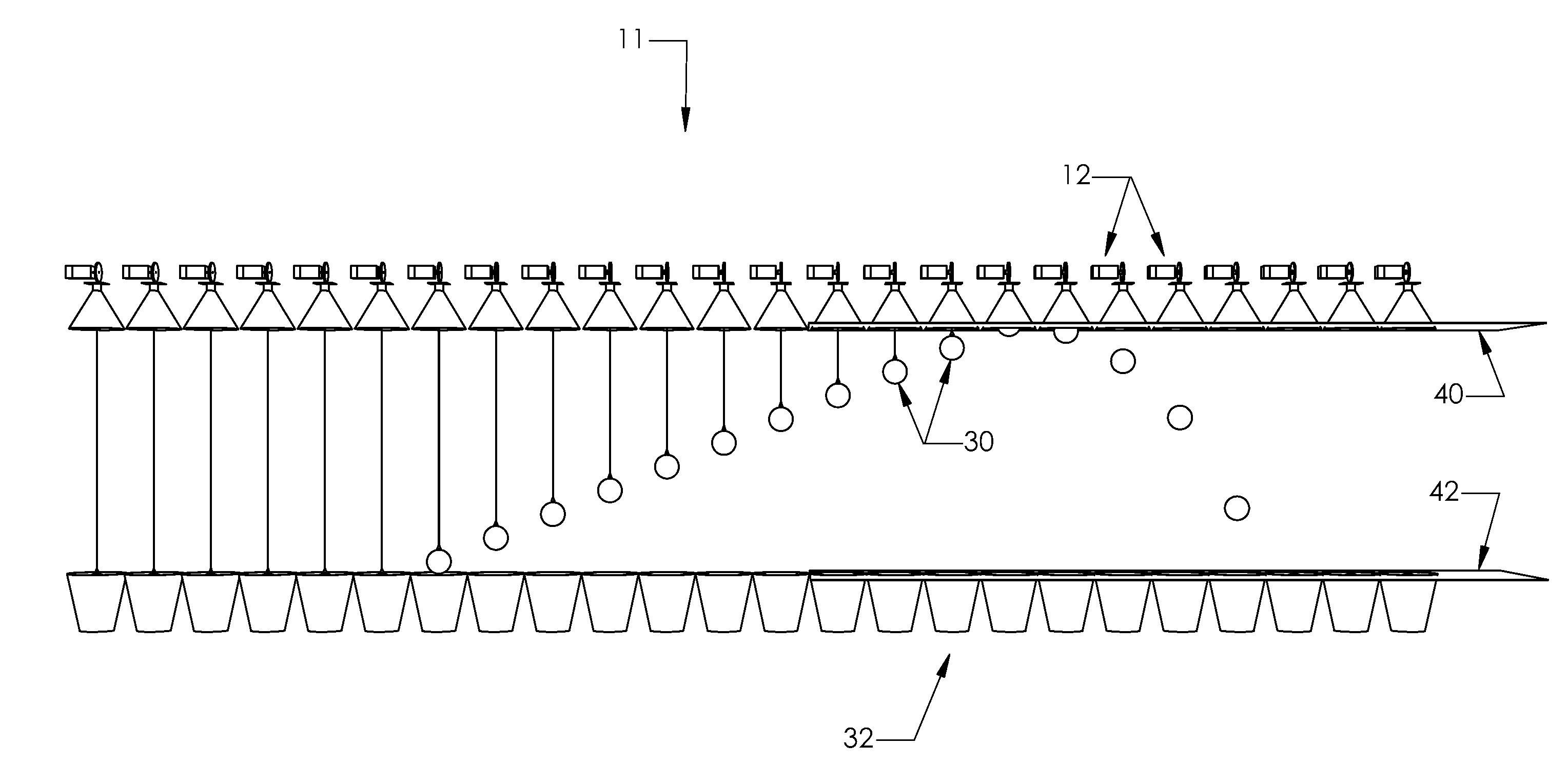
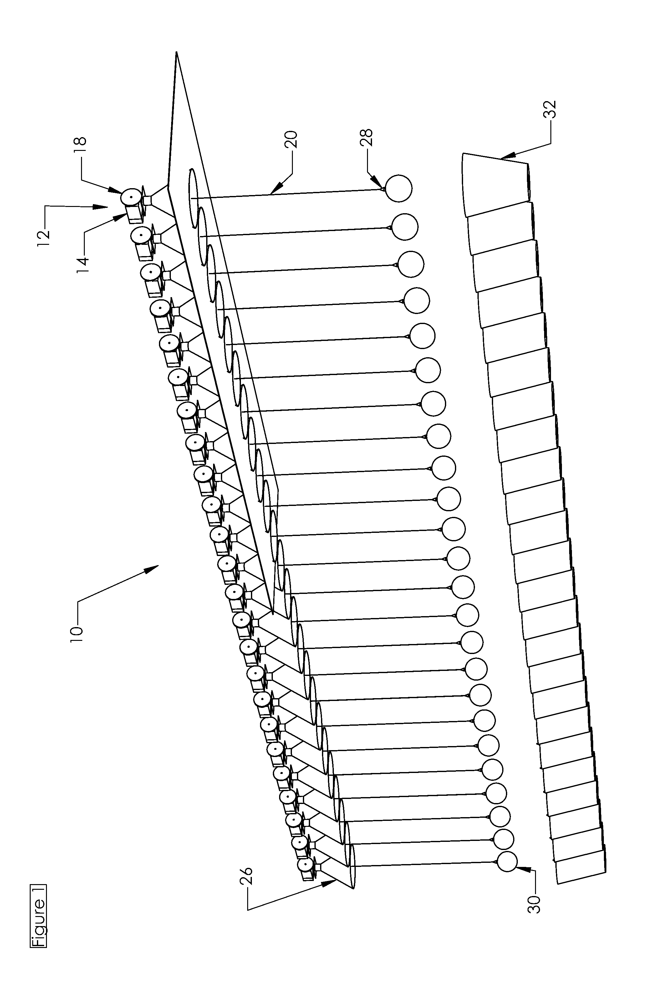
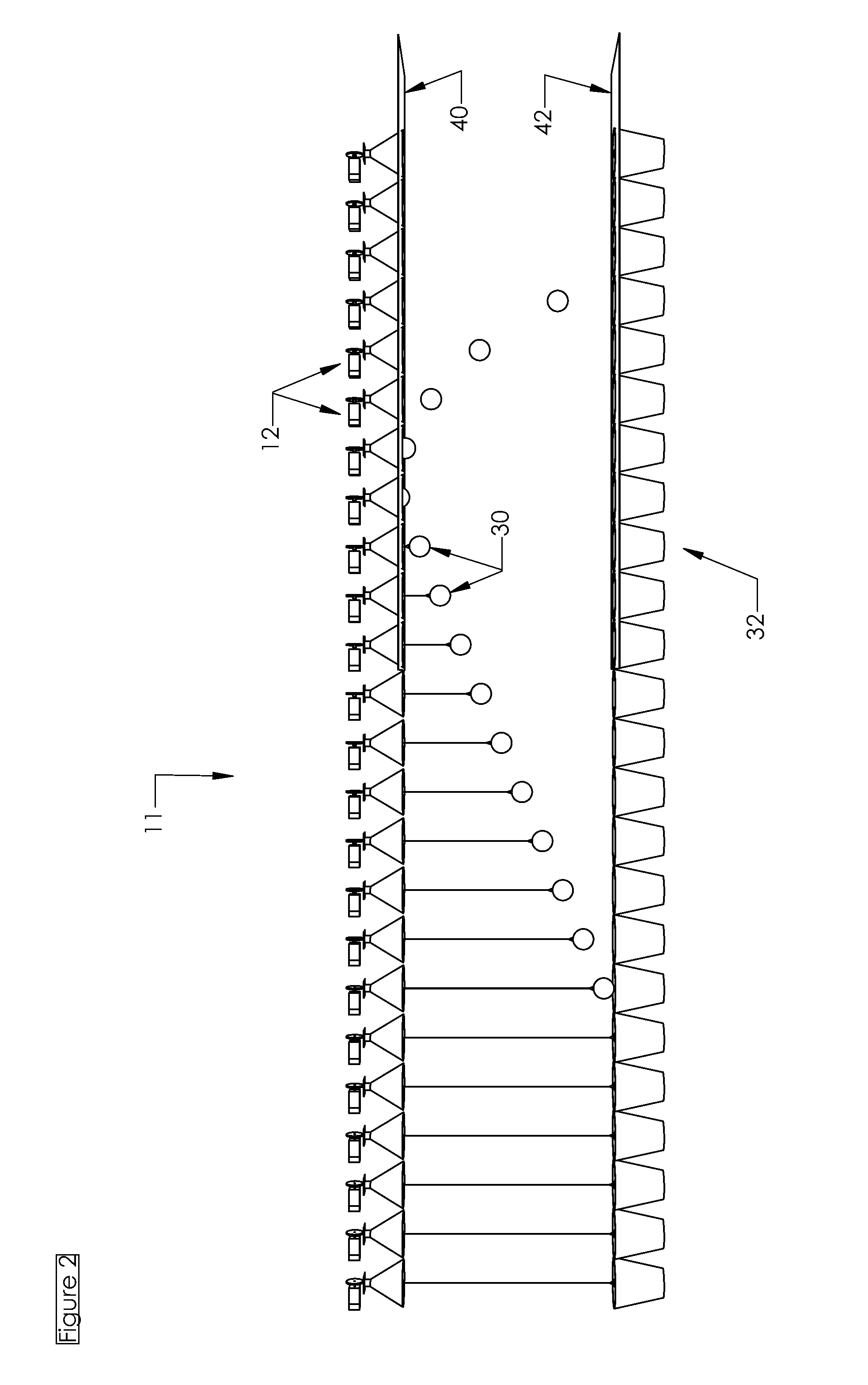
[0025]Referring to FIG. 1, an apparatus for repetitively lifting and lowering objects 10 in accordance with the invention is shown. Apparatus 10 includes a plurality of kinetic releasing elements 12 (as best seen in FIG. 3) equally spaced in this embodiment in a linear pattern. Each kinetic releasing element 12 includes a top unit 14. Top unit 14 supports the remainder of the kinetic releasing element and houses a motor 16. Each kinetic releasing element also includes a rotary member in the form of a pulley 18 connected to the motor through a motor shaft 17 and a cord 20 attached at its distal end 22 to the outer ci...


PUM


Abstract

An apparatus for repetitively lifting and lowering objects to create visual patterns having a plurality of units each with a motor, a rotary member, a cord attached at its distal end to the circumferential edge of the rotary member, an attaching mechanism affixed to the proximal end of the cord, and an object removably connected to the attaching mechanism. A computer or microprocessor is provided and programmed to selectively rotate the rotary members to move the objects between selected pre-determined positions along a generally vertical path of travel to establish a geometric pattern of repetitive elements.

Description

CROSS-REFERENCE TO RELATED PATENT APPLICATIONS[0001]This patent application claims the benefit of U.S. Provisional Patent Application No. 61 / 215,031, filed May 1, 2009.FIELD OF THE INVENTION[0002]This invention relates generally to positioning multiple objects in a space and, more particularly, to methods and apparatus for moving multiple objects in space in unique new ways to create kinetic imagery.BACKGROUND OF THE INVENTION[0003]From almost the inception of kinetic art, people have been interested in moving objects in space and time in order to create visual effects. For centuries, this art form relied on human / solar / wind / magnetic powered motion. For most of the twentieth century it has been limited primarily to single speed art pieces. While more complex kinetic art became possible when transmissions could be used to vary speed, still kinetic art pieces have been limited to a discreet small number of speeds.BRIEF SUMMARY OF THE INVENTION[0004]This invention involves an apparatus...

Claims


Application Information

Patent Timeline
Patent Type & Authority Applications(United States)
IPC IPC(8): G09F27/00G09F11/10
CPCG09F19/10G09F19/02G09F27/00G09F19/12
Inventor PENTLAND, JOSEPH
Owner PENTLAND JOSEPH
Why Eureka
Try Eureka