Stylus pen and touch sensing system and driving method of the same

a technology of touch sensing and stylus, which is applied in the direction of instruments, computing, electric digital data processing, etc., can solve the problems of synchronization distortion, difficult touch position detection, and increase in manufacturing costs

Active Publication Date: 2017-02-02
LG DISPLAY CO LTD
View PDF3 Cites 35 Cited by
  • Summary
  • Abstract
  • Description
  • Claims
  • Application Information

AI Technical Summary

Benefits of technology

[0015]An object of the present invention is to provide a touch sensing system which has a stylus pen that generates a pen driving signal based on a touchscreen driving signal from a touchscreen and applies it to the touchscreen, and which allows the pen driving signal to be precisely synchronized with the touchscreen driving signal regardless of the proximity between the stylus pen and the touchscreen, and a driving method of the same.

Problems solved by technology

With the passive stylus, touch position detection is difficult because the changes in capacitance at contact points with the touchscreen are very subtle.
In this technology, the touch module requires a sensing circuit for receiving the pen driving signal, which results in a rise in manufacturing costs.
However, if the strength of the touchscreen driving signal received by the stylus pen changes depending on the proximity between the touchscreen and the stylus pen, the synchronization is distorted.
Once the synchronization between the pen driving signal and the touchscreen driving signal is distorted, the touch sensing signal becomes weaker, thus leading to low touch performance.

Method used


Image

  • Stylus pen and touch sensing system and driving method of the same
  • Stylus pen and touch sensing system and driving method of the same
  • Stylus pen and touch sensing system and driving method of the same

Examples


Embodiment Construction

[0037]Hereinafter, exemplary embodiments of the present invention will be described in detail with reference to the accompanying drawings. Throughout the specification, the same reference numerals indicate substantially the same components. In describing the present invention, when it is deemed that a detailed description of known functions or configurations may unnecessarily obscure the subject matter of the present invention, the detailed description will be omitted.

[0038][Touch Sensing System]

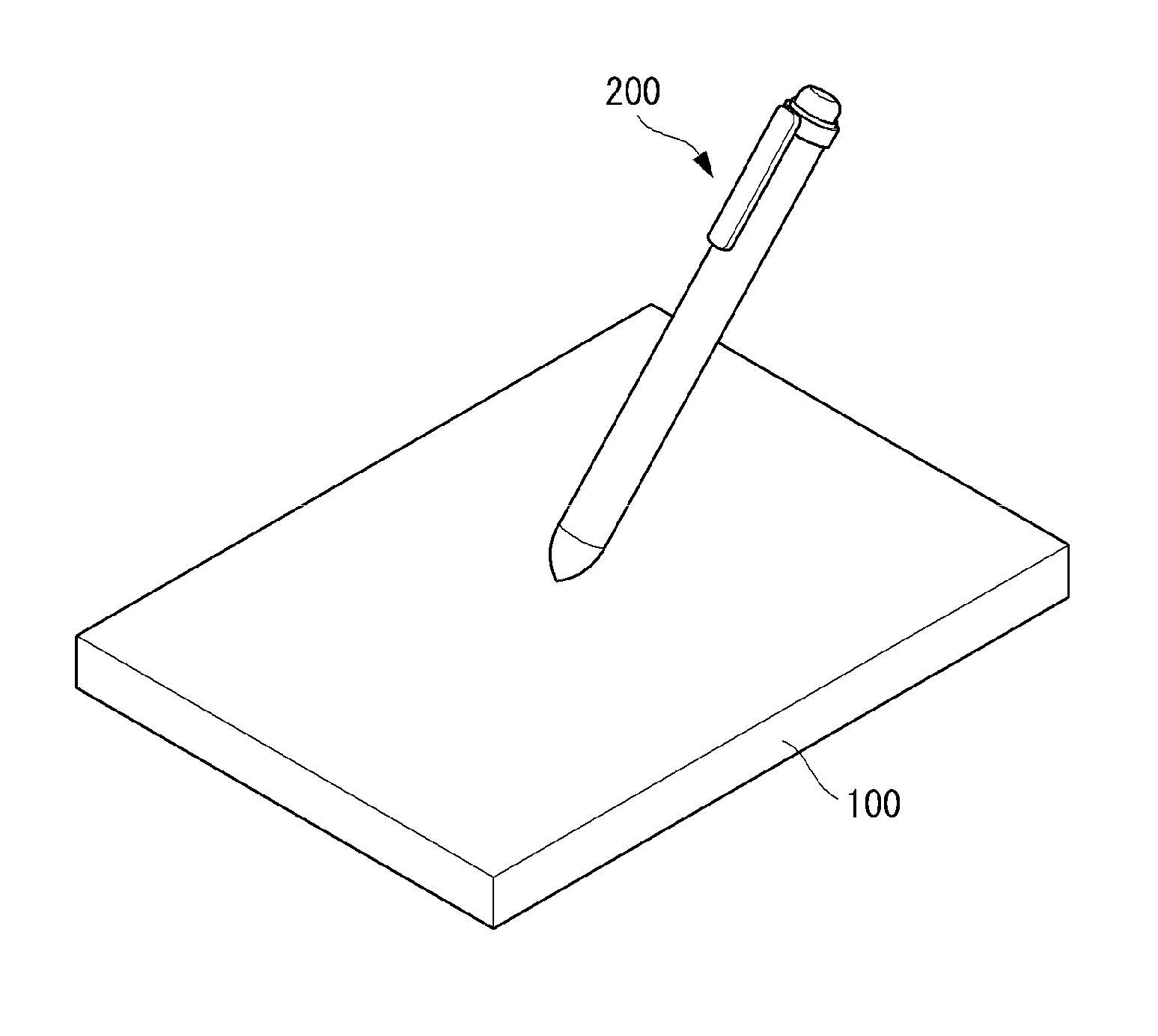
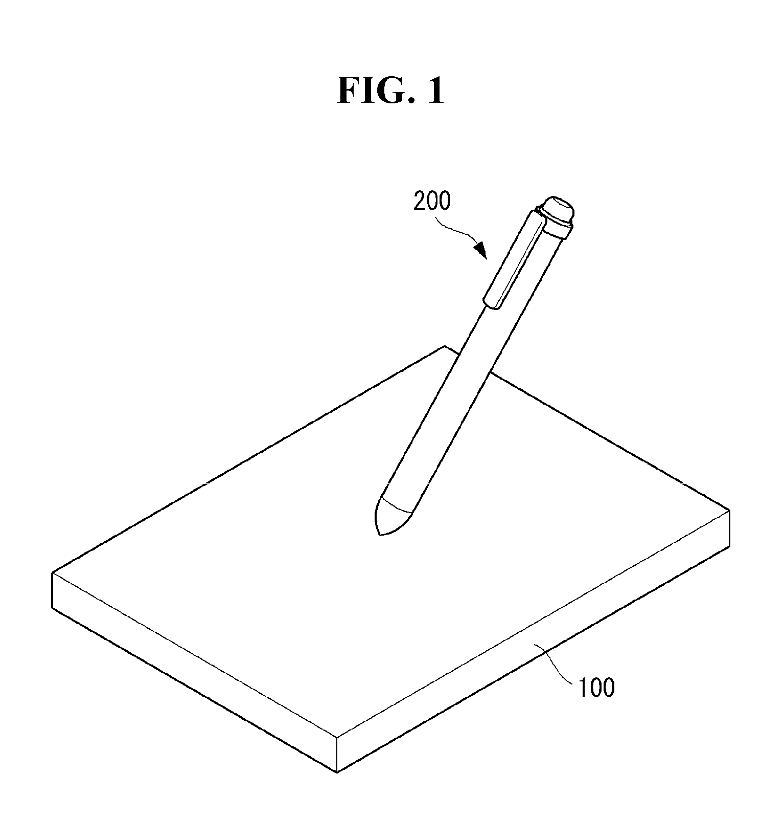
[0039]FIG. 1 shows a touch sensing system according to an exemplary embodiment of the present invention.

[0040]Referring to FIG. 1, a touch sensing system according to the present invention comprises a display device 100 and a stylus pen 200.

[0041]The display device 100 has both a display function and a touch sensing function. The display device 100 has a built-in capacitive touchscreen that can sense touch when a finger or a conductive object such as the stylus pen 200 hovers over or touches...


PUM


Abstract

A touch sensing system comprises a touchscreen with a plurality of touch electrodes, to which a touchscreen driving signal is applied, and a stylus pen that generates a pen driving signal based on the touchscreen driving signal and sends the same to the touchscreen. The stylus pen comprises: an amplifier that amplifies the touchscreen driving signal to generate an amplified signal; a comparator that compares the amplified signal with a preset reference voltage to generate a comparator output signal; and a signal processor that measures the pulse width of the comparator output signal, adjusts an amount of delay based on a measurement, and determines an output timing of the pen driving signal based on an adjusted amount of delay to synchronize the pen driving signal with the touchscreen driving signal.

Description

[0001]This application claims the priority benefit of Korean Patent Application No. 10-2015-0108839 filed on Jul. 31, 2015, which is incorporated herein by reference for all purposes as if fully set forth herein.BACKGROUND OF THE INVENTION[0002]Field of the Invention[0003]This document relates to a touch sensing system, and more particularly, to a touch sensing system capable of touch input from a stylus pen and a driving method of the same.[0004]Discussion of the Related Art[0005]User interfaces (UI) enable humans (users) to easily control various types of electronic devices as they want. Typical examples of the user interfaces include keypads, keyboards, mice, on-screen displays (OSD), and remote controllers with an infrared communication capability or radio frequency (RF) communication capability. The user interface technology is continuing to make progress toward higher user sensitivity and ease of operation. Recently, user interfaces have been evolving into touch UI, voice reco...

Claims


Application Information

Patent Timeline
Patent Type & Authority Applications(United States)
IPC IPC(8): G06F3/038G06F3/041G06F3/0354G06F3/044
CPCG06F3/0383G06F3/044G06F2203/04108G06F3/03545G06F3/0412G06F3/0418G06F3/0416G06F2203/04112G06F3/0442G06F3/0443
Inventor JUNG, DOYOUNGJANG, HYUNGUKKIM, SUNGCHULBAE, SANGHYUCKHAN, SUNGSUJU, SUYUN
Owner LG DISPLAY CO LTD
Why Eureka
Try Eureka