Controller for a brushless motor

a brushless motor and control board technology, applied in the direction of dynamo-electric machines, synchronous motor starters, ac motor stoppers, etc., can solve the problems of adversely affecting the performance of the motor system, and achieve the effect of accurate synchronization of excitation and freewheeling with the rotor position

Inactive Publication Date: 2011-10-20
DYSON TECH LTD
View PDF22 Cites 35 Cited by
  • Summary
  • Abstract
  • Description
  • Claims
  • Application Information

AI Technical Summary

Benefits of technology

[0019]The motor system may comprise a position sensor coupled to the input of the controller. The position sensor senses the position of a rotor of the brushless motor and outputs a position-sensor signal. As a result, accurate synchronization of excitation and freewheeling with rotor position may be achieved.

Problems solved by technology

This delay may in turn adversely affect the performance of the motor system.

Method used


Image

  • Controller for a brushless motor
  • Controller for a brushless motor
  • Controller for a brushless motor

Examples


specific example

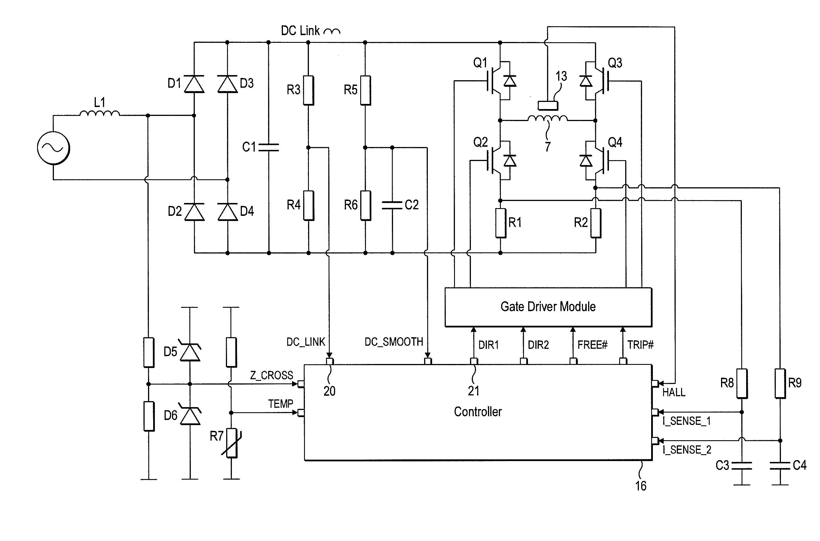
[0243]A particular embodiment of the motor system 1 will now be described by way of example only. Values for various hardware components of the motor system 1 are detailed in FIG. 19, while FIG. 20 lists various constants and thresholds employed by the controller 16. FIGS. 21 and 22 detail the flux-linkage characteristics of the link inductor L1 and the motor 2.

[0244]As illustrated in FIG. 23, the motor system 1 has seven modes of operation: Fault, Initialization, Stationary, Low-Speed Acceleration, Mid-Speed Acceleration, High-Speed Acceleration, and Running. Accordingly, in comparison to that previously described and illustrated in FIG. 8, the motor system 1 has one additional mode of operation.

[0245]Fault, Initialization, Stationary and Low-Speed Acceleration Modes are unchanged from that previously described. Mid-Speed Acceleration Mode corresponds to the previously-described High-Speed Acceleration Mode. Consequently, when operating in Mid-Speed Acceleration Mode, the controlle...


PUM


Abstract

A controller for a brushless motor that includes a processor, a first timer, a second timer, a compare register, a comparator, an input, and one or more outputs. The processor starts the first timer in response to a signal at the input. The first timer then generates an interrupt after a first period. In response to the interrupt, the processor generates a first control signal at the outputs. The processor also loads the compare register and starts the second timer in response to either the input signal or the interrupt. The comparator then generates a second control signal at the outputs when the second timer and the compare register correspond. Additionally, a motor system that includes the controller.

Description

REFERENCE TO RELATED APPLICATIONS[0001]This application claims the priority of United Kingdom Application No. 1006392.3, filed Apr. 16, 2010, the entire contents of which are incorporated herein by reference.FIELD OF THE INVENTION[0002]The present invention relates to a controller for a brushless motor.BACKGROUND OF THE INVENTION[0003]The control system of a brushless motor typically includes a controller that generates control signals for exciting and freewheeling phase windings of the motor. The controller will often use interrupts and timers to generate the control signals at times relative to edges of a rotor signal. For example, each edge of the rotor signal may generate a first interrupt. In response to the first interrupt, the controller may load a first timer with a first value and a second timer with a second value. When the first timer overflows a second interrupt is generated, which causes the controller to generate a control signal for exciting the phase winding. When th...

Claims


Application Information

Patent Timeline
Patent Type & Authority Applications(United States)
IPC IPC(8): G05B15/00
CPCH02P2209/07H02P6/14H02P6/15H02P6/17H02P6/34H02P6/16H02P6/18
Inventor HAWKER, DAVID JOHNDAI, HANPING
Owner DYSON TECH LTD
Why Eureka
Try Eureka