Cold plate with pins

a technology of cold plate and pin, which is applied in the direction of laminated elements, lighting and heating equipment, separation processes, etc., can solve the problems of plugging of cold plate, not being particularly clean,

Inactive Publication Date: 2011-04-07
WOLVERINE TUBE INC
View PDF45 Cites 77 Cited by
  • Summary
  • Abstract
  • Description
  • Claims
  • Application Information

AI Technical Summary

Problems solved by technology

Some important factors include cost of production and ease of producing relatively large quantities.
In som

Method used


Image

  • Cold plate with pins
  • Cold plate with pins
  • Cold plate with pins

Examples


Embodiment Construction

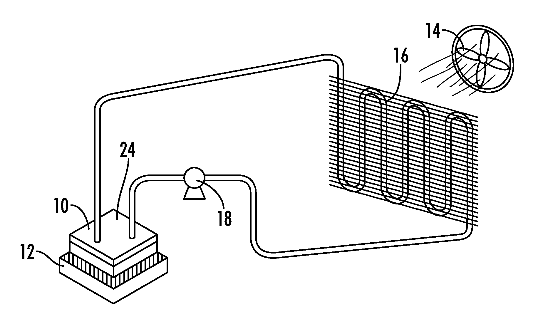
[0021]Some electronic components are limited by the heat they produce. Cooling can help to increase the utilization of some of these components. Different cooling techniques are more appropriate for different equipment or different circumstances. One cooling method uses fans to blow air over an electronic component for convection cooling. This technique is simple and safe, but does not provide the cooling potential of some other techniques. The utilization of a liquid coolant can provide more efficient cooling, but many electronic components can malfunction when splashed with a liquid, so some can be cautious when using liquid cooling. Nevertheless, liquid cooling can increase the overall efficiency of some electronic components, as well as providing certain other benefits. Secondary benefits can include decreased acoustical noise and superior temperature consistency in the electronic component.

Heat Transfer Fundamentals

[0022]This description will focus on single phase heat transfer...


PUM

PropertyMeasurementUnit
Lengthaaaaaaaaaa
Widthaaaaaaaaaa
Areaaaaaaaaaaa

Abstract

A cold plate includes an enclosure with an inlet, an outlet, a base and a lid. The inlet and outlet are in fluid communication, so fluid can flow from the inlet though the enclosure to the outlet. The base is formed from a base plate, and the base plate includes an island facing into the enclosure. A plurality of pins extends from the island toward the lid. The pins can have a spiral shape, where the cross sectional profile of the pins change along the length of the pin.

Description

BACKGROUND OF THE INVENTION[0001]1. Field of the Invention[0002]This invention relates to the production and use of a cold plate, which is used to transfer heat.[0003]2. Description of the Related Art[0004]Certain electronic devices generate heat as they operate, and this heat has to be removed or dissipated for the device to continue operating properly. Several techniques have been used to cool electronic equipment. Examples include fans, which are used to blow air over electronic equipment. This air serves to convectively cool the electronic equipment with normal ambient air. Other techniques that have been used include liquid cold plates. Liquid cold plates are plates with channels through which liquid flows. The electronic equipment is mounted in contact with a liquid cold plate and the heat generated by the electronic equipment is transferred to the coolant inside the plate. This can provide better cooling than the convective cooling provided by a fan with considerably less flo...

Claims


Application Information

Patent Timeline
IPC IPC(8): F28F7/00B21D53/02
CPCF28F3/022H01L21/4878H01L23/3677H01L23/473Y10T29/4935H01L2924/0002F28F3/048H01L2924/00B21J5/068Y10T29/49359H01L29/70H05K7/20B01D8/00B23P15/26H05K7/20254
Inventor LOONG, SY-JENQSMITH, DONALD LYNN
Owner WOLVERINE TUBE INC
Why Eureka
Try Eureka