Inflatable interspinous spacer

a spacer and interspinous technology, applied in the field of orthopedics, can solve problems such as loss of therapeutic effect, and achieve the effect of soft and more deformabl

Active Publication Date: 2011-04-07
DEPUY SYNTHES PROD INC
View PDF52 Cites 50 Cited by
  • Summary
  • Abstract
  • Description
  • Claims
  • Application Information

AI Technical Summary

Benefits of technology

[0009]In the insertable deflated condition, the spacer is preferably laterally insertable into the interspinous space between adjacent spinal processes without substantially altering the spinal processes such that at least a portion of the central portion of the first balloon and at least a portion of the second balloon is located in the interspinous space between the adjacent spinous processes. In the inflated expanded condition, the height of the first and second end portions of the first balloon are larger than the height of the central portion of the first balloon. That is, the first and second end portions of the first balloon have first and second heights, respectively, and the central portion of the first balloon has a third height, the first and second heights of the first and second end portions are larger than the third height of the central portion when in the inflated expanded condition. Accordingly, the spacer in the inflated expanded condition may form an “H” or dumbbell-like shape or form. In addition, in the inflated expanded condition, the first and second end portions of the first balloon are preferably located along the lateral sides of the adjacent spinous processes to retain the spacer in position between the spinous processes, the second balloon is disposed over the central portion of the first balloon, and the second balloon is preferably less rigid than the first balloon. The second balloon and the central portion of the first balloon in the inflated expanded condition and when located between the spinous processes may limit extension of the spine. The compressive modulus of the second filler material may be less than the compressive modulus of the first filler material.
[0010]The expansion of the second balloon may distract and expand the interspinous space between the adjacent spinous processes where the spacer is located. The second balloon may form a hollow substantially cylindrical shape disposed about the central portion of the first balloon and may form a common wall or surface with at least a portion of the central portion of the first balloon. The second balloon may also be disposed over at least a portion of the first end portion and the second end portion. The second balloon may be manufactured from a low-compliant material so that upon inflation, the second balloon assumes a predetermined shape. Alternatively however the second balloon is preferably manufactured with a non-predetermined shape upon inflation. For example, the second balloon is preferably manufactured from a semi-compliant or highly compliant material so that the second balloon may elastically or plastically stretch so as to conform to the shape of the spinous processes to increase the surface area contact between the spacer and the inferior and superior surfaces of the adjacent spinous processes. The second balloon may absorb compressive shocks to the spacer. The spacer without the first or second filler materials contained within the first and second balloons may be insertable within a cannula having a 5 mm inside diameter.

Problems solved by technology

There is an increasing concern, supported by recent clinical study data, that suggests hard spacers may subside into the bony spinous processes over time, thus losing their therapeutic effect.

Method used


Image

  • Inflatable interspinous spacer
  • Inflatable interspinous spacer
  • Inflatable interspinous spacer

Examples


Embodiment Construction

[0020]Certain terminology is used in the following description for convenience only and is not limiting. The words “right”, “left”, “lower”, “upper”, “top” and “bottom” designate directions in the drawings to which reference is made. The words “inwardly” and “outwardly” refer to directions toward and away from, respectively, the geometric center of the spacer, and designated parts thereof. The words, “anterior”, “posterior”, “superior”, “inferior”, “lateral”, “medial” and related words and / or phrases designate preferred positions and orientations in the human body to which reference is made and are not meant to be limiting. The terminology includes the above-listed words, derivatives thereof and words of similar import.

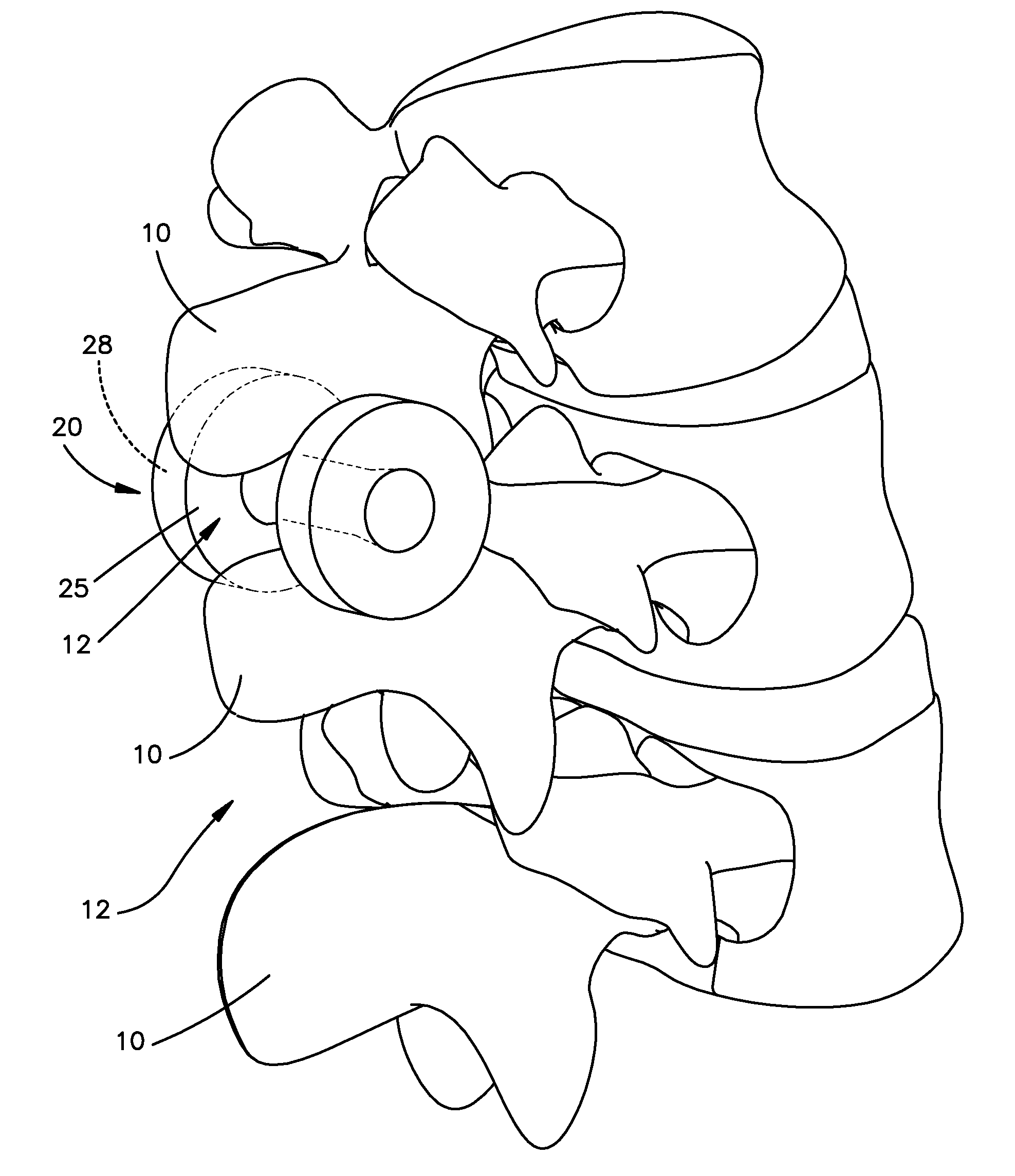
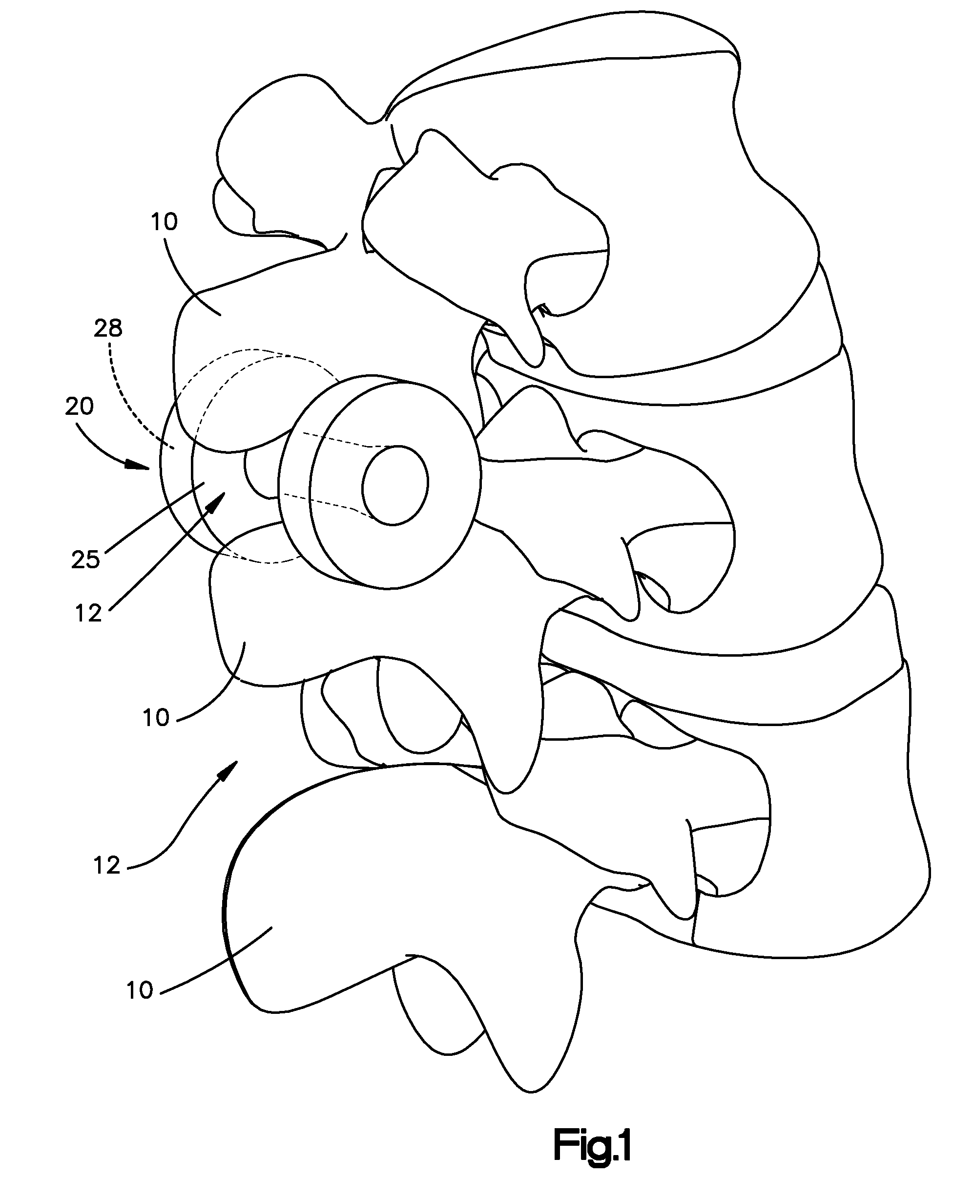
[0021]FIG. 1 illustrates an inflatable interspinous spacer 20 that includes a housing 25 and an injectable filler material 28. The spacer 20 is preferably inserted into the interspinous space 12 in a deflated nonexpanded state, and is inflated or otherwise expanded wi...


PUM


Abstract

The present invention is directed to an inflated interspinous spacer. The interspinous spacer is inserted into the interspinous space between adjacent spinous process in a deflated or unexpanded state, and is inflated or expanded with an injectable filler material. Upon inflation, the spacer preferably distracts the spinous processes and assumes a shape that retains the spacer in position and preferably mechanically locks with the spinous processes. The spacer includes two separate balloons configured to have different compressive modulus so that one balloon is softer and more deformable than the other balloon.

Description

CROSS REFERENCE TO RELATED APPLICATIONS[0001]This application claims priority to U.S. Provisional Patent Application No. 61 / 057,985, filed Jun. 2, 2008, the contents of which are hereby incorporated by reference in its entirety.FIELD OF THE INVENTION[0002]The present invention relates generally to orthopedics. More specifically, the present invention relates to an inflatable interspinous spacer preferably insertable via a minimally invasive surgical procedure.BACKGROUND OF THE INVENTION[0003]Interspinous spacers are indicated for the treatment of spinal stenosis and treatment of low back pain caused by, for example, disc- or facet-related degeneration. Interspinous spacers may be configured to distract and / or maintain the spacing between adjacent superior and inferior spinous processes above and below the painful disc level.[0004]Most interspinous spacers in clinical use are made of a hard, undeformable material under normal physiological loads, such as metal or PEEK. There is an in...

Claims


Application Information

Patent Timeline
Patent Type & Authority Applications(United States)
IPC IPC(8): A61B17/70
CPCA61B2017/00557A61B17/7065
Inventor SINGHATAT, WAMISCHOW, DAVIDSMITH, NIGEL G.FUSSELL, GARLAND W.
Owner DEPUY SYNTHES PROD INC
Why Eureka
Try Eureka