Devices and methods to disintegrate foods

a technology of foods and devices, applied in the direction of grain treatment, manufacturing tools, centrifuges, etc., can solve the problems of reducing the efficiency of the process, affecting the safety of the same users, and difficult to clean

Active Publication Date: 2011-04-14
BACKUS ALAN
View PDF10 Cites 64 Cited by
  • Summary
  • Abstract
  • Description
  • Claims
  • Application Information

AI Technical Summary

Problems solved by technology

To begin with, their truncated conical filter screens load up very quickly with pulp which reduces their efficiency and is very difficult to clean, especially if the pulp clogged in the screens is not cleaned immediately after juicing.
Ironically, the new larger feed chutes found on newer centrifugal juicers, which offer convenience to juicer users, also introduce a safety hazard to the same users because the size of the new chutes is large enough to allow a child's hand to pass through the chute and into contact with the rapidly rotating shredder disc.
A further typical disadvantage of current centrifugal juicers is that a liquid collecting receptacle must be placed adjacent to the juicer to catch juices immediately as the juice is produced, because these juicers generally do not have any onboard ability to collect and store juices.
These juice collecting receptacles usually have the disadvantage that fresh juices collected within them typically separate within a few minutes thus losing their fresh taste and pleasing appearance.
Further, many centrifugal type juicers have low pour spouts which don't permit normal height glasses to be placed beneath them.
Those juicers that have pour spouts which are high enough to fill a normal height glass, are generally difficult to store due to the juicer's height.
In addition, many juicers force their users to waste precious time before removing their glass while waiting for the juicer's pour spouts to stop dripping after juice has been dispensed.
Another typical disadvantage of current centrifugal type juicers is that particles of the foods fed down the feed chute can hit the fast spinning shredding disc and be thrown back at high speed through the feed chute at the juicer user causing messes on the user and / or adjacent countertops, as well as resulting in a safety hazard to the juicer user from being hit by fast-moving ejected food particles.
Centrifugal type juicers also can get jammed on food because there is no way to move the food around in relationship to the shredding disc.
Such pushing may relieve the problem, or it may compact the food within the chute and make the problem worse.
Juicing efficiency within juicers is always an issue because it affects the cost of juice produced.
Centrifugal juicers are only moderately efficient when compared with other designs, because they leave significant amounts of juice and moisture within their waste.
Efficiency is also lost because shredding of the food within a centrifugal juicer takes place in only one stage so any juice which is not extracted at this first and only stage is permanently lost.
Many of the disadvantages of centrifugal juicers are shared in common with other food preparation devices such as, but not limited to, blenders and food processors.
Such disadvantages include, but are not limited to, issues involving feeding foods into the device, extracting processed foods from the device, the height of ejector chutes, as well as other safety, use and storage issues.

Method used


Image

  • Devices and methods to disintegrate foods
  • Devices and methods to disintegrate foods
  • Devices and methods to disintegrate foods

Examples


embodiment one

Exemplary Preferred Embodiment One

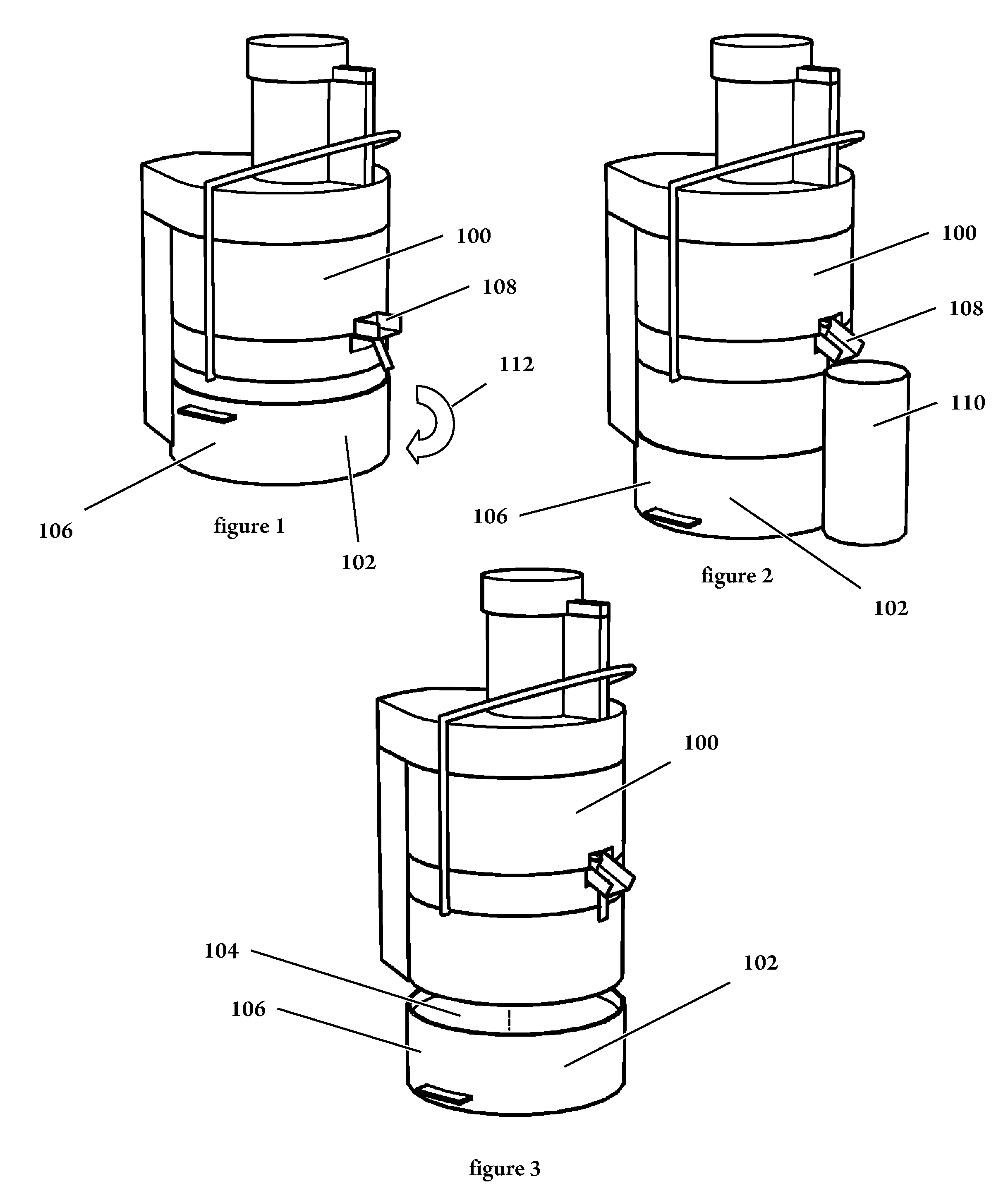
[0165]Referring to FIGS. 1 through 3, food preparation device 100 is supported by base 102. Food preparation device 100 may be a centrifugal type juice extractor as illustrated, or it may be an alternative such as by way of a non-limiting examples, a food processor or blender or other type of food processing device. Base 102 has generally vertical sidewalls 106 at its periphery. Generally horizontal partition 104 is asymmetrically placed vertically within vertical sidewalls 106 and divides the space within vertical sidewalls 106 into 2 concavities, one being shallow and the other being deep and occupying most of the interior space defined by sidewalls 106. Generally horizontal partition 104 may be contiguous or may have openings penetrating some or most of its surface. Vertical sidewalls 106 are spaced wide enough apart to allow food preparation device 102 to telescope within vertical sidewalls 106.

[0166]FIG. 1 shows when food preparation device 100...

embodiment two

Exemplary Preferred Embodiment Two

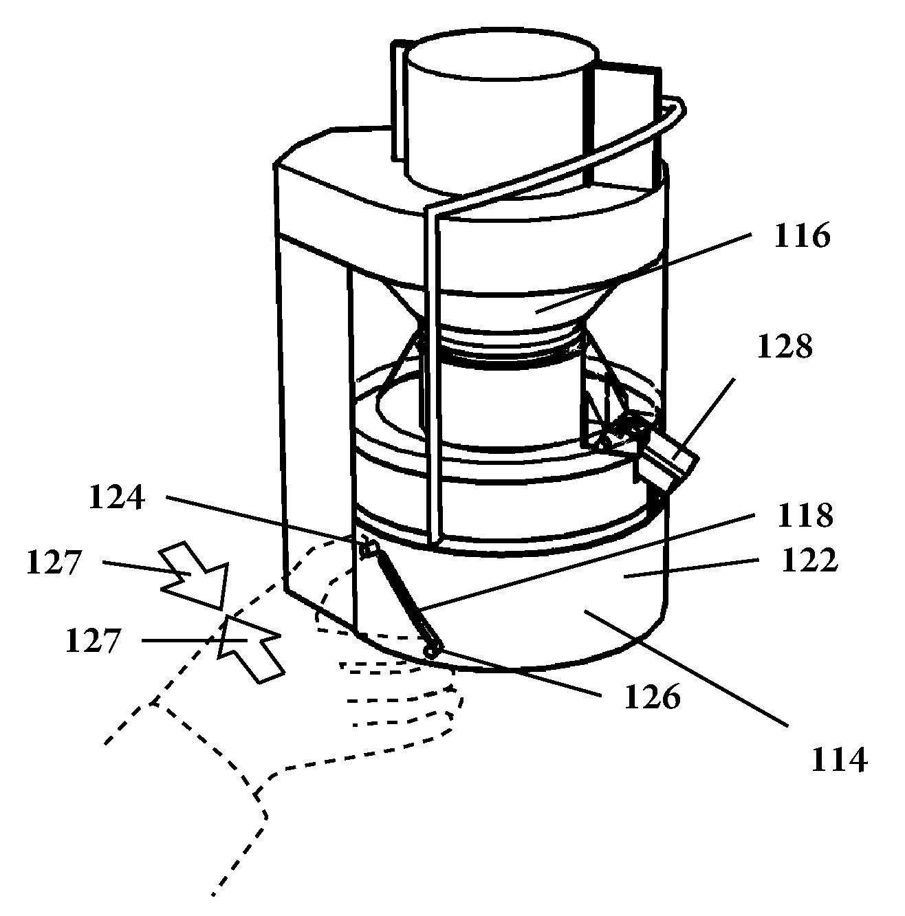
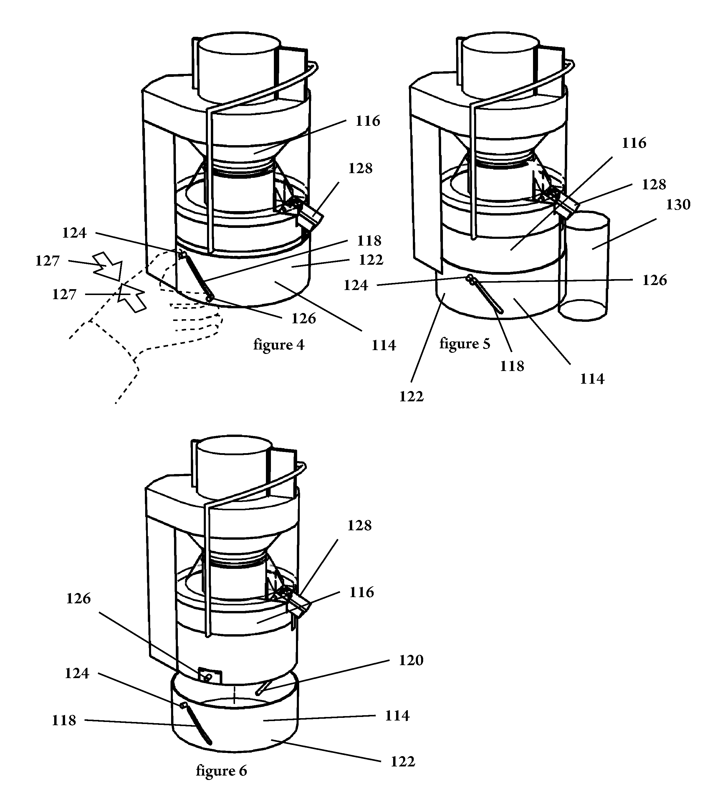
[0169]FIGS. 4 through 6 illustrate adjustable height base 114 used to elevate and lower food preparation device 116. As shown in FIG. 6, base 114 includes helical slots 118 and 120 which penetrate through generally vertical sidewalls 122. At the top of helical slots 118 and 120 are two finger grips which mirror each other, and only one of which, finger grip 124, is shown. As is shown in FIG. 6 as well, food preparation device 116 also has finger grip 126, which has a counterpart which is replicated on the opposite side of food preparation device 116.

[0170]As shown in FIGS. 4 and 5, food preparation device 116 telescopes within adjustable height base 114. As also shown in FIGS. 4 and 5, finger grip 126 projects through helical slot 118, and, not shown, its opposite side counterpart projects through helical slot 120. When finger grip 126 is squeezed 127 toward finger grip 124, and their opposite side counterparts are simultaneously squeezed toward one...

embodiment three

Exemplary Preferred Embodiment Three

[0173]FIGS. 7 through 9, and including FIG. 9 enlargement 9A, show another preferred embodiment. Here, food preparation device 132 telescopes inside of, and raises and lowers vertically within, base 134 allowing taller liquid collecting receptacles, such as exemplary glass 136 to be placed below pour spout 138. Latch actuation button 140 is biased outward and rides within slot 142. This arrangement is imaged on the opposite side of base 134 and food preparation device 132 where a latch actuation button which is not shown rides within slot 144. Food preparation device 132 is raised within base 134 by finger pressure pulling latch actuation button 140 toward finger rest 146 and simultaneously doing the same action with the latch actuation button not shown and finger rest 148. Latch claws 150 grip detents on the interior of sidewalls 152 to hold food preparation device 132 in its raised position. Pressing in on latch actuation button 140 and the oppo...


PUM


Abstract

The subject application is directed to a food processing device to extract juice. The device includes an inlet coupled to a disintegrator. The inlet is configured to accept food items and the disintegrator configured to disintegrate food items passed through the inlet. The device further includes a separator that accepts the disintegrated food items and separates out the liquid components from the food item. The device further includes a reservoir that is coupled to the separator for accepting and holding the liquid components. The reservoir includes a translucent member for viewing of liquid levels within the reservoir, and a valved outlet. The valved outlet is configured to allow or prevent the flow of liquid from the reservoir through the valved outlet.

Description

CROSS-REFERENCE TO RELATED APPLICATIONS[0001]This application is a continuation of U.S. patent application Ser. No. 12 / 577,483, filed Oct. 12, 2009.FIELD OF THE INVENTION[0002]The subject application is directed toward devices which extract pulp and juice as well as other constituent components from foods such as fruits and vegetables.BACKGROUND OF INVENTION[0003]Devices to disintegrate foods are very common today. Such devices include, but are not limited to: juicers, blenders, and food processors. Essentially, these devices feed foods, including, but not limited to, fruits and vegetables, into a machine which mechanically disintegrates the foods. Many of these devices have feed chutes. Also shared in common by many of these devices is a rotating shredder element which chops and / or grinds the foods.[0004]One of the most common devices to disintegrate foods is the centrifugal type juicer. These devices typically have a generally vertical feed chute which is open at the top and termi...

Claims


Application Information

Patent Timeline
Patent Type & Authority Applications(United States)
IPC IPC(8): A23N1/02B02C19/00B02C23/04
CPCA47J19/027A23N1/003A23N1/00A23N1/02
Inventor BACKUS, ALAN
Owner BACKUS ALAN
Why Eureka
Try Eureka