Transformer based voltage combiner with inductive shunt

Inactive Publication Date: 2011-04-14
SNAPTRACK
View PDF2 Cites 1 Cited by
  • Summary
  • Abstract
  • Description
  • Claims
  • Application Information

AI Technical Summary

Benefits of technology

[0022]The voltage combiner may further include means for directing the DC current to the bypass path. Said means may be a resistor connected between the first tap and the inductor. Said means may further include a capacitor in parallel with the resistor to

Problems solved by technology

As such, the amplifier may exhibit low overall efficiency.
DC current flowing in the transformer windings may result in saturation of the core, with a consequent loss of magnetising inductance, which is clearly undesirable.
However, increasing core size increases the transformer leakage inductance and reduces the high frequency response of the transformer and in turn, reduces the high frequency response of the power supply.
An alternative technique for avoiding saturation is to introduce an airgap in the core, but this increases the number of turns required to achieve a given low frequency performance and indirectly increases the leakage inductance, and again reduces the high frequency response of the supply.
However, this requires control systems to monitor the currents in both the secondary and primary windings of the transformer, and is complex and difficult to control.

Method used


Image

  • Transformer based voltage combiner with inductive shunt
  • Transformer based voltage combiner with inductive shunt
  • Transformer based voltage combiner with inductive shunt

Examples


Embodiment Construction

[0033]The present invention is described herein by way of particular examples and specifically with reference to a preferred embodiment. It will be understood by one skilled in the art that the invention is not limited to the details of the specific embodiments given herein. In particular the invention is described herein by way of reference to the provision of a power supply for an RF amplification stage. However more generally the invention may apply to any arrangement where it is necessary to reduce DC current in a transformer winding, and particularly in a transformer in which an AC signal and a DC signal are combined.

[0034]It should be noted that where the same reference numerals are used in different Figures, they refer to the same elements.

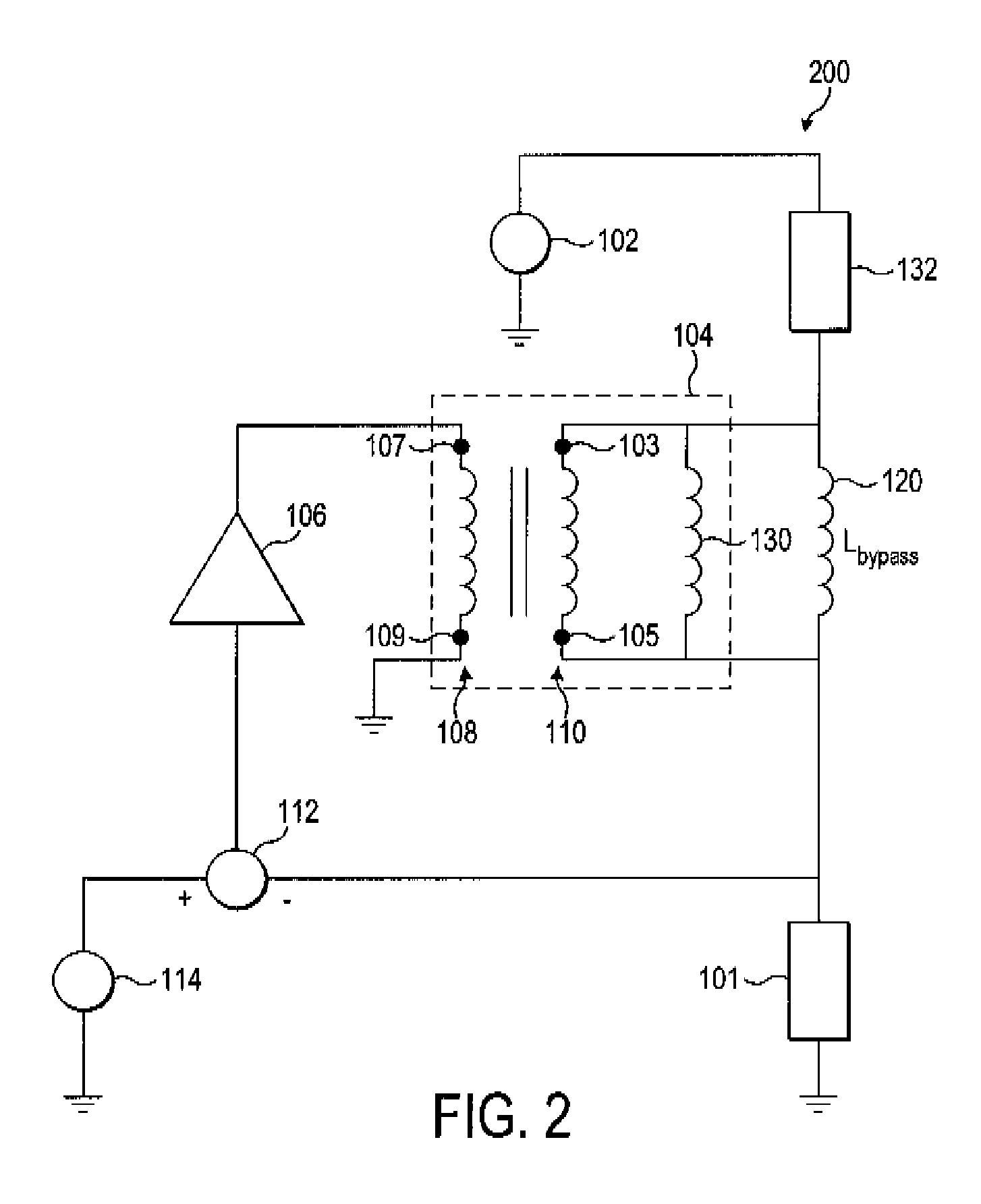
[0035]Referring to FIG. 2, there is illustrated a transformer based power supply 200 which may be used for modulating the power supplied to a power amplifier in an envelope tracking system, in accordance with the general principles of the p...


PUM


Abstract

In accordance with the invention there is also provided a voltage combiner (200) comprising: a transformer (104) having a first (108) and second (110) winding each having a first and second tap; and an inductor (120) connected between the first and second taps of the second winding, wherein: the first tap of the first winding is adapted for connection to a first voltage (114), the first tap of the second winding is adapted for connection to a second voltage (102), and the second tap of the second winding is adapted to provide an output being the first and second voltages combined, and further wherein: the inductor (120) is adapted to provide a bypass path for the current associated with the second voltage. (102)

Description

FIELD OF THE INVENTION [0001]The present invention relates to a combiner for combining signals, preferably for combining an AC signal with a DC signal. The invention is concerned particularly, but not exclusively, with modulatable power supplies including a combiner implemented as a transformer.BACKGROUND TO THE INVENTION [0002]Transistor amplifiers have a peak efficiency for a particular input power that is a function of geometry (i.e. circuit components and layout), load and supply voltage. In conventional radio frequency (RF) power amplification these characteristics are fixed based on the peak input level expected. For amplifiers presented with an input signal having a wide dynamic range, the input signal infrequently achieves peak levels and frequently operates below peak levels. As such, the amplifier may exhibit low overall efficiency.[0003]Various techniques are known in the art for enhancing amplifier efficiency based on the supply voltage. One broad classification of solut...

Claims


Application Information

Patent Timeline
IPC IPC(8): G05F3/04H01F27/29
CPCH01F27/34H01F27/42H03F2200/504H03F1/0211H03F1/0227H02M1/40H03F1/0216
Inventor WIMPENNY, GERARD
Owner SNAPTRACK
Why Eureka
Try Eureka