

Touch panel structure and method for manufacturing the same, and display apparatus and method for manufacturing the same
- Summary
- Abstract
- Description
- Claims
- Application Information
AI Technical Summary
Benefits of technology
Problems solved by technology
Method used
Image

Examples
first preferred embodiment
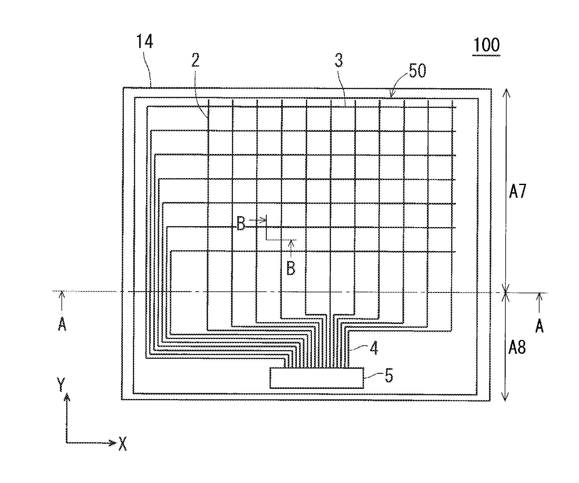
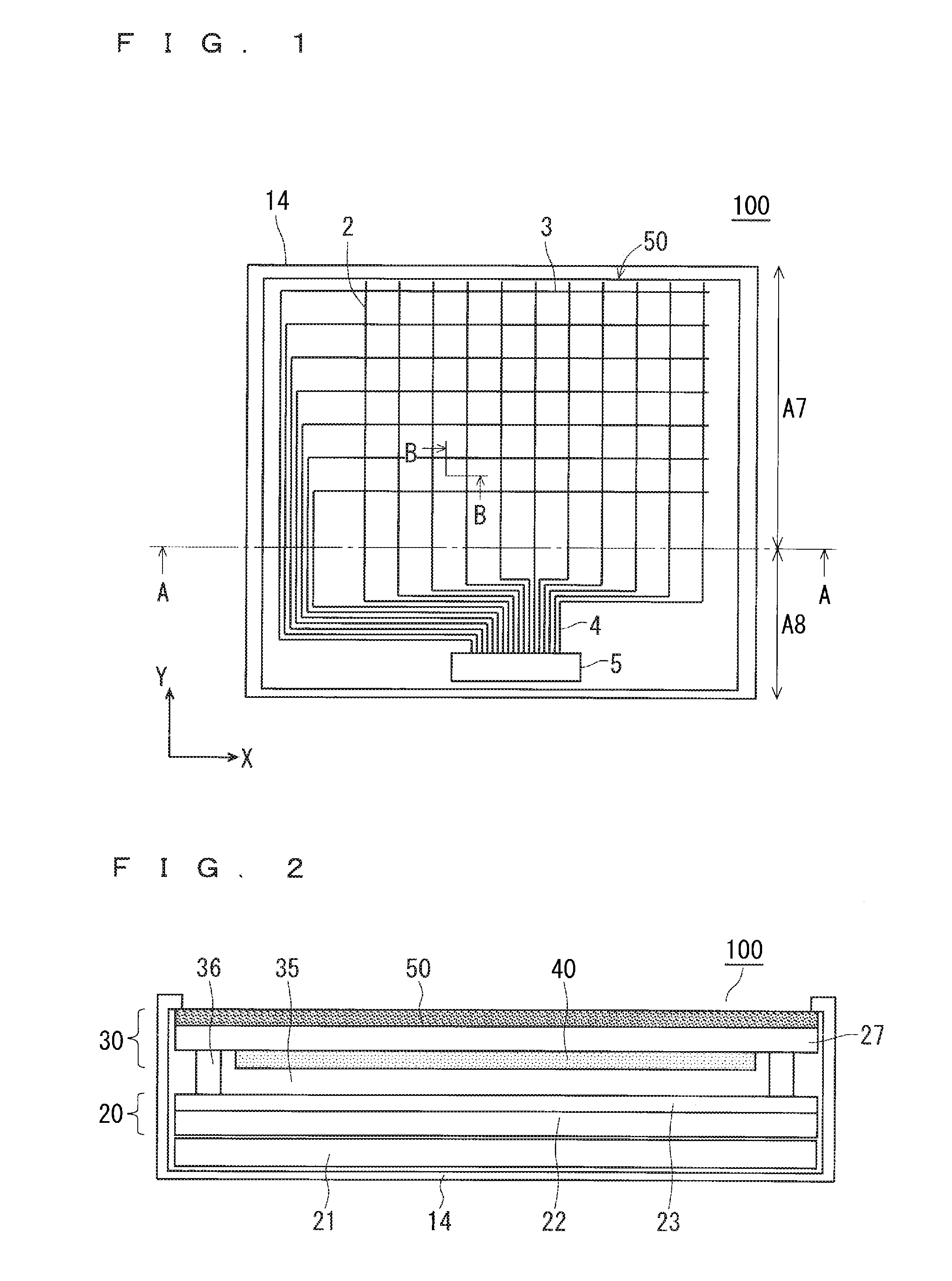
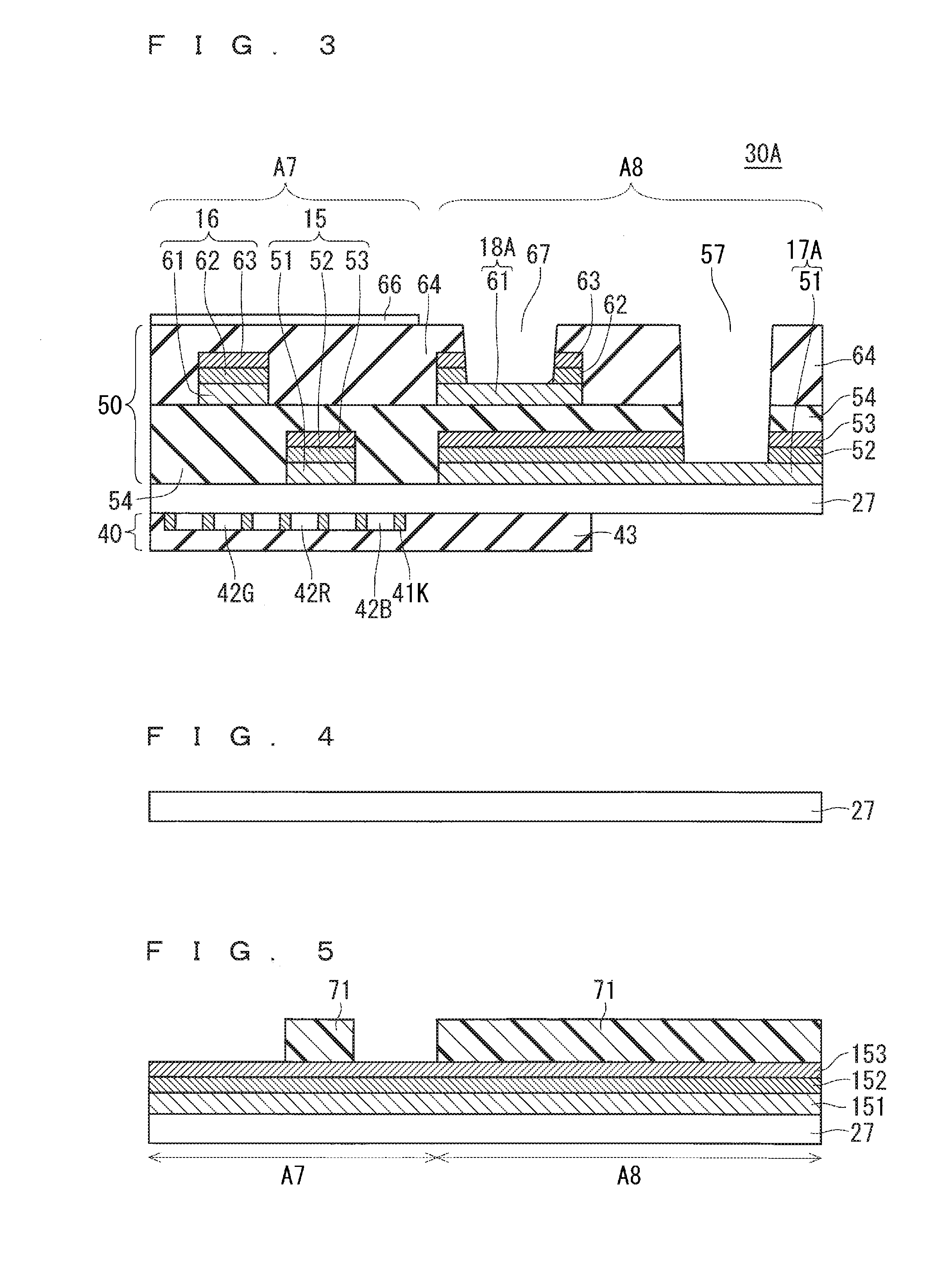
[0041]Hereinafter, with reference to the cross-sectional structure of the display apparatus 100, the CF-equipped touch panel substrate 30A (touch panel structure) in the first preferred embodiment of the present invention is described. FIG. 3 is a cross-sectional view showing a B-B section in a display region A7 in FIG. 1 and a cross-sectional structure of the first preferred embodiment in which each terminal portion in a lead-out wiring region A8 for the X position detecting wires 2 and the Y position detecting wires 3 is extracted and abstract.
[0042]As shown in FIG. 3, the touch sensor layer 50 includes a low-resistance conductive film 51 (first conductive film) selectively formed, a low-reflection film 52 (first low-reflection film) on the low-resistance conductive film 51, and a transparent cap film 53 (first transparent film) on the low-reflection film 52 on the surface (one main surface) of the transparent substrate 27 made of glass or PET in the display region A7. A lower-lay...
second preferred embodiment
[0128]Hereinafter, with reference to the cross-sectional structure of the display apparatus 100, the CF-equipped touch panel substrate 30B (touch panel structure) in a second preferred embodiment of the present invention is described. FIG. 24 is a cross-sectional view showing the B-B section in the display region A7 in FIG. 1 and a cross-sectional structure of the second preferred embodiment in which each terminal portion in the lead-out wiring region A8 for the X position detecting wires 2 and the Y position detecting wires 3 is extracted and abstract. Hereinafter, the same components as those of the CF-equipped touch panel substrate 30A in the first preferred embodiment are denoted by the same references, descriptions are appropriately omitted, and differences between the first preferred embodiment and this preferred embodiment are mainly described.
[0129]A contact hole 57M (opening) is formed in the lead-out wiring region A8 while penetrating the protective insulating film 64, the...
PUM
 Abstract
Description
Claims
Application Information