
Face Spline For a Driven Wheel Hub

Active Publication Date: 2008-07-24
SCHAEFFLER TECH AG & CO KG
View PDF10 Cites 11 Cited by
  • Summary
  • Abstract
  • Description
  • Claims
  • Application Information

AI Technical Summary

Benefits of technology

[0014]The theoretical tooth root width is in each case the spacing between two mutually adjacent cut edges on the tooth root side.
[0015]By way of the above-mentioned geometry, a predetermined breaking point is provided in the face spline on the wheel hub bearing in the torque connection between the joint shaft and the wheel, which predetermined breaking point is arranged away from parts which are relevant to safety, for example in a manner which is remote from the wheel bearing. As a result, the overall cross section of the material of the face spline, which overall cross section is loaded by torques about the rotational axis, has a lower resistance to deformations, which lower resistance leads to yielding deformation of the spline in a targeted manner in the case of torques which are produced by overloading. Each further cross section of the material of the wheel hub which is loaded by the same torques and is remote from the face spline has higher section moduli. The overall cross section is the sum of all the individual cross sections of the teeth, tooth roots and/or cross sections in the material of the wheel hub at the transitions to the teeth, which individual cross sections are loaded proportionally by torques at the same time with the action of the respective overall torque. Therefore, in the case of overloading, in the worst case the drive to the wheel hub is interrupted by destruction of the tooth engagement, but the wheel bearing remains intact.
[0016]As an alternative, the pair comprising the face splines is designed as a safety ratchet coupling. The wheel hub and the drive element are clamped axially with prestress against one another by means of at least one threaded bolt. Overall or at e

Problems solved by technology

The rigid configuration for transmitting high torques to the wheel can have a disadvantageous effect when, in the ca

Method used


Image

  • Face Spline For a Driven Wheel Hub
  • Face Spline For a Driven Wheel Hub
  • Face Spline For a Driven Wheel Hub

Examples


Example

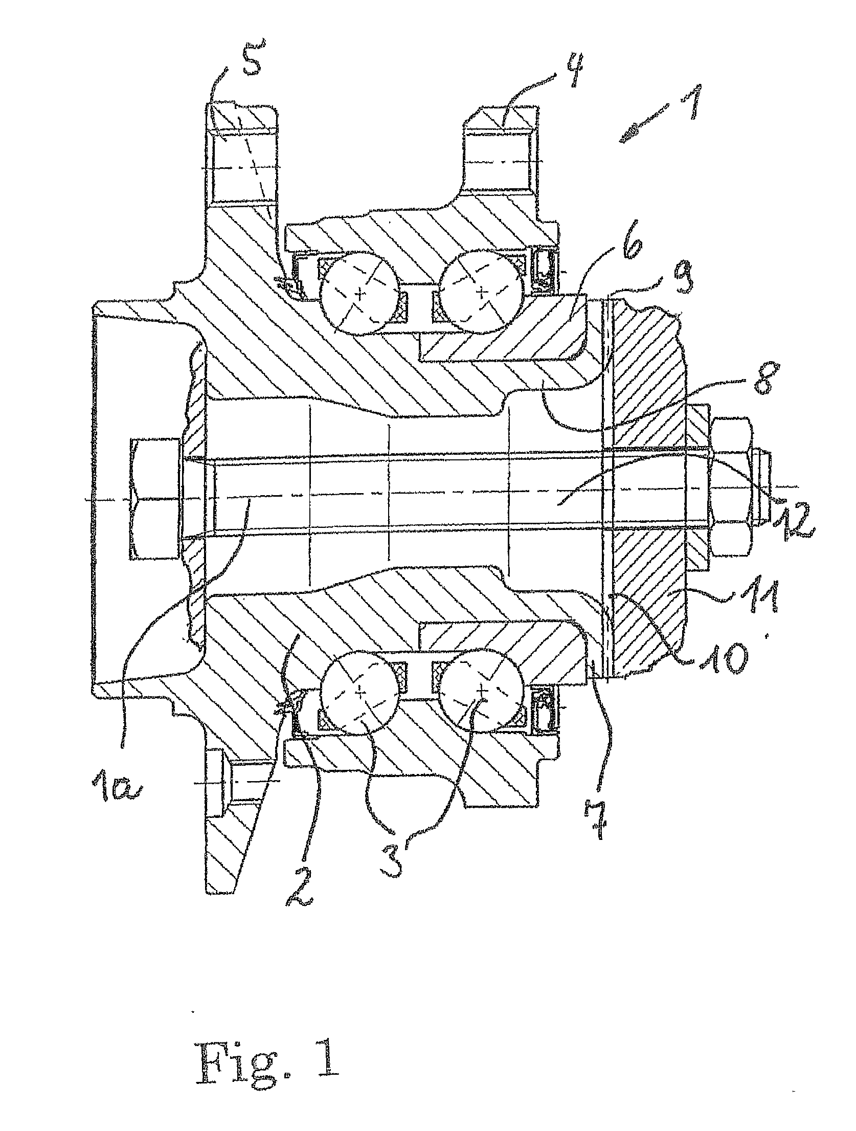
[0021]One exemplary embodiment of a face spline 9 according to the invention is made in that side of the collar 7 which faces in the axial direction without cutting by forming, such as cold extrusion, stamping or rolling. The face spline is paired with a corresponding mating spline 10 on a drive element 11 (not shown in further detail). The splines 9 and 10 have the same number of teeth 13 as one another, face one another axially, engage without play into one another and are clamped axially inside one another and against one another by means of a threaded bolt 12.

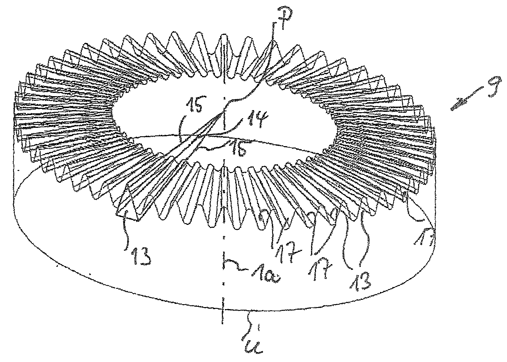
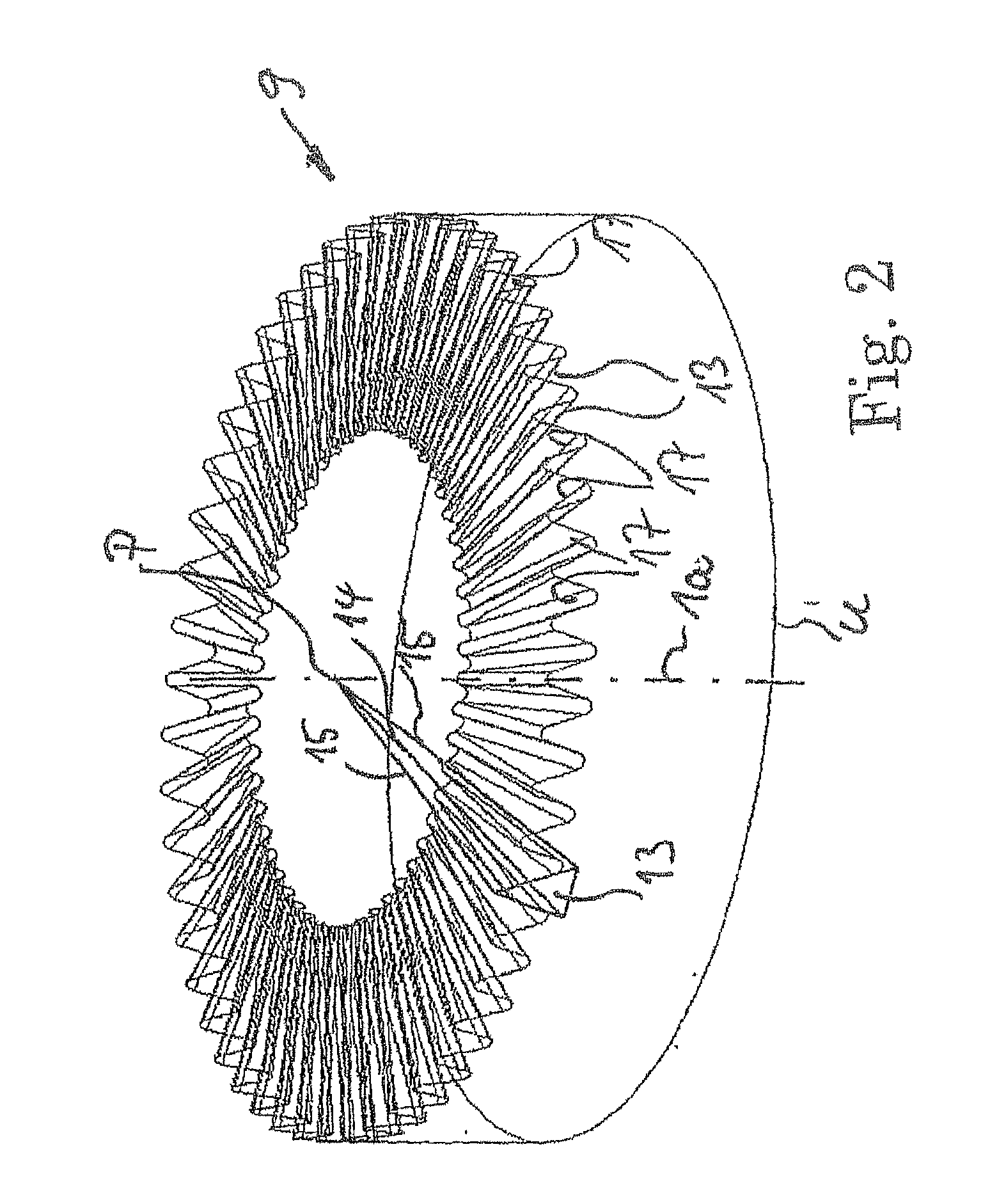
[0022]Exemplary embodiments of the splines 9 and 10 are shown in simplified form in FIGS. 2, 2a and 3. FIG. 2 shows the spline 9, 10 in perspective and also shows here how the individual tooth 13 of wedge-shaped configuration is described on the tip, root and flank side by radially oriented geometric lines 14, 15, 16 which meet at the intersection point P. The intersection point P is the common intersection point for all ra...


PUM


Abstract

The invention relates to a face spline of a toothed rim running in the circumferential direction around a rotation axis on a wheel-bearing arrangement for a driven wheel hub. The face spline is provided for play-free engagement with the counter-spline, facing the face spline and the teeth of the face spline have a wedge-like embodiment such that the geometrical lines of the face spline meet centrally at a common point on the rotation axis and the teeth thus run in the radial direction on the rotation axis.

Description

FIELD OF THE INVENTION [0001]The invention relates to a face spline of a toothed rim which extends about a rotational axis in the circumferential direction on a wheel bearing arrangement for a driven wheel hub, the face spline being provided for playfree engagement into the mating spline which faces the face spline, and the teeth of the face spline being of wedge-shaped configuration in such a way that the geometric lines of the face spline meet centrally at a common point on the rotational axis and the teeth therefore extend in the radial direction toward the rotational axis.BACKGROUND OF THE INVENTION [0002]A face spline of this type is described in further detail in DE 31 16 720 C1. A corresponding mating spline of a drive shaft of the vehicle engages into the face spline. The mating spline is formed as a rule on a bell or a stub of a bell of a constant velocity joint.[0003]During the assembly of the drive element into the wheel hub arrangement, the drive element and the wheel hu...

Claims


Application Information

Patent Timeline
IPC IPC(8): F16D13/60F16C13/02
CPCB60B27/0005B60B27/0031B60B27/0084F16C43/04F16C19/186F16D1/076B60B27/0094F16C2326/02B60B27/06B60B27/00
Inventor LANGER, ROLANDNIEBLING, PETERMASUR, ERNSTHEISS, RALFFUELLER, BENNO
Owner SCHAEFFLER TECH AG & CO KG
Learn More