Retaining Structure

Active Publication Date: 2011-04-14
LIU MIN SHENG +3
View PDF2 Cites 37 Cited by
  • Summary
  • Abstract
  • Description
  • Claims
  • Application Information

AI Technical Summary

Benefits of technology

[0006]The primary object of the present invention is to provide a retaining

Problems solved by technology

It is to be noted that a tenon is used to retain two adjacent parts together, or a recessed portion is formed on a wooden first part and a raised po

Method used


Image

  • Retaining Structure
  • Retaining Structure
  • Retaining Structure

Examples


first embodiment

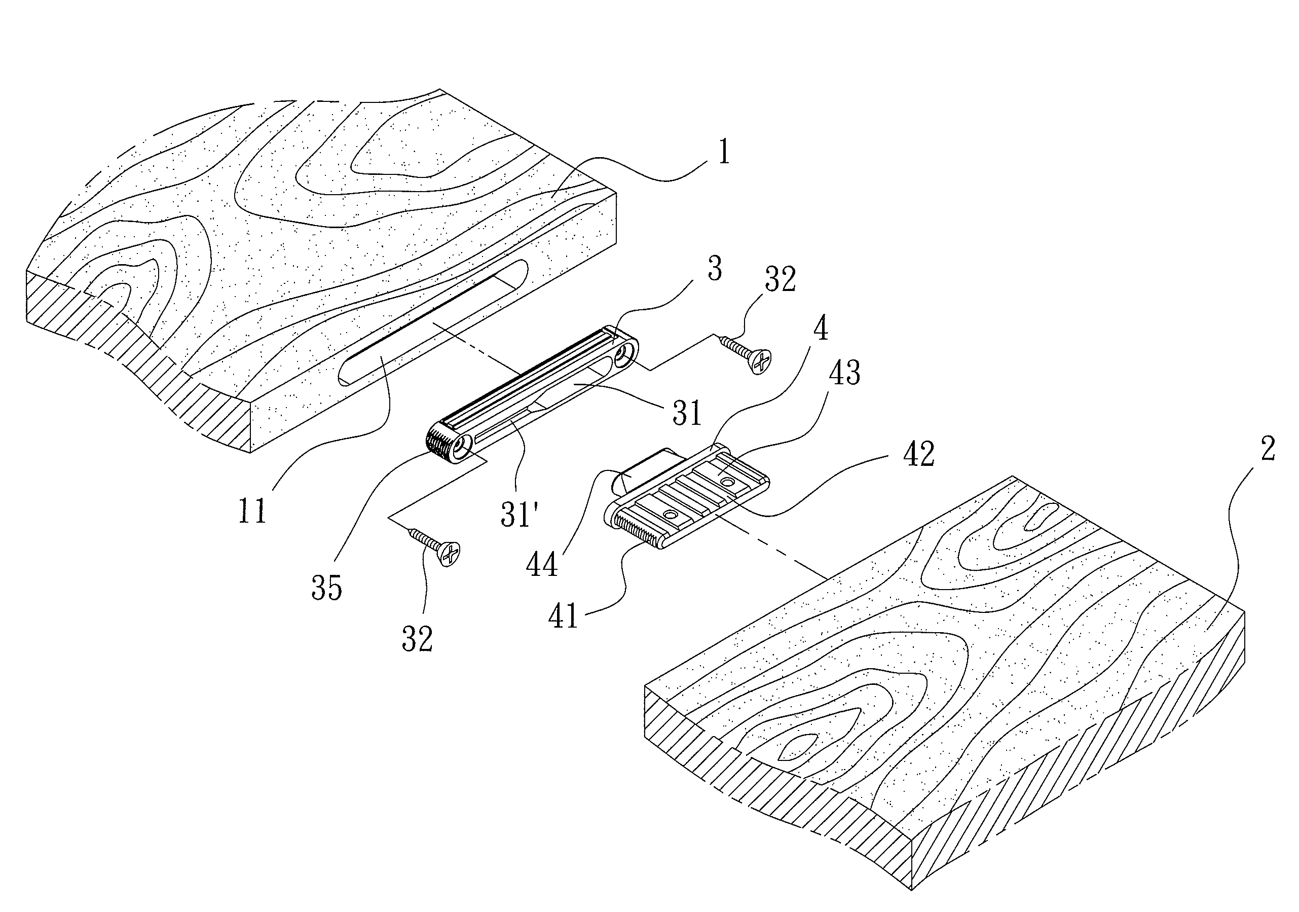
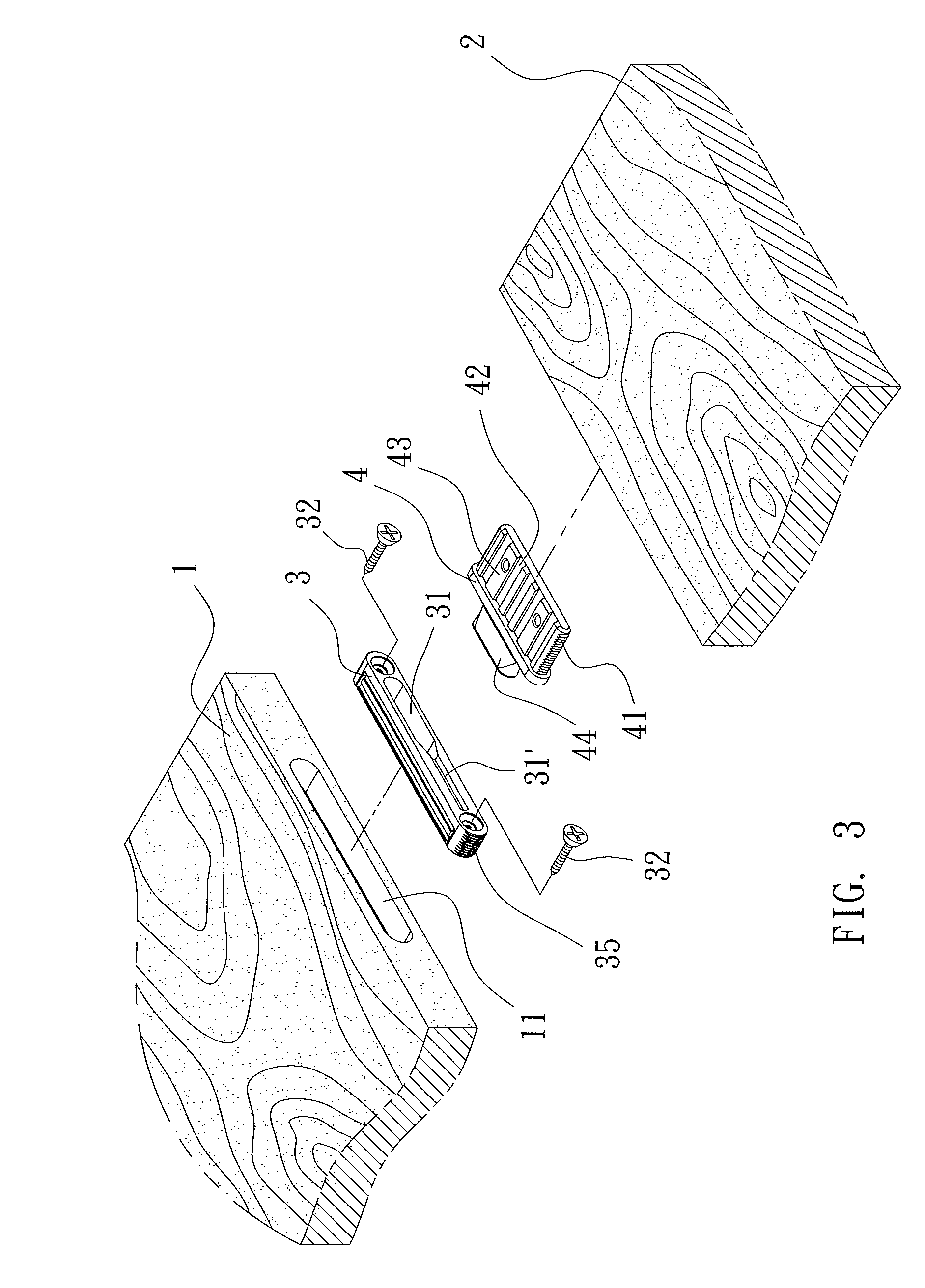
[0034]Referring to FIGS. 3-4, a retaining structure in accordance with the present invention is used to retain a wooden first part 1 with a wooden second part 2 together and comprises a retainer 3 fitted to a recess 11 of the first part 1 (and then the retainer 3 is fixed by using screw elements 32, as shown in FIGS. 4A and 4B), and comprises a fastening member 4 to be engaged with the second part 2 having a support 44 extending outward from the fastening member 4 so as to be retained to a notch 31 of the retainer 3, thereby assembling the first and the second parts 1, 2 together. The improvement of the retaining structure includes:

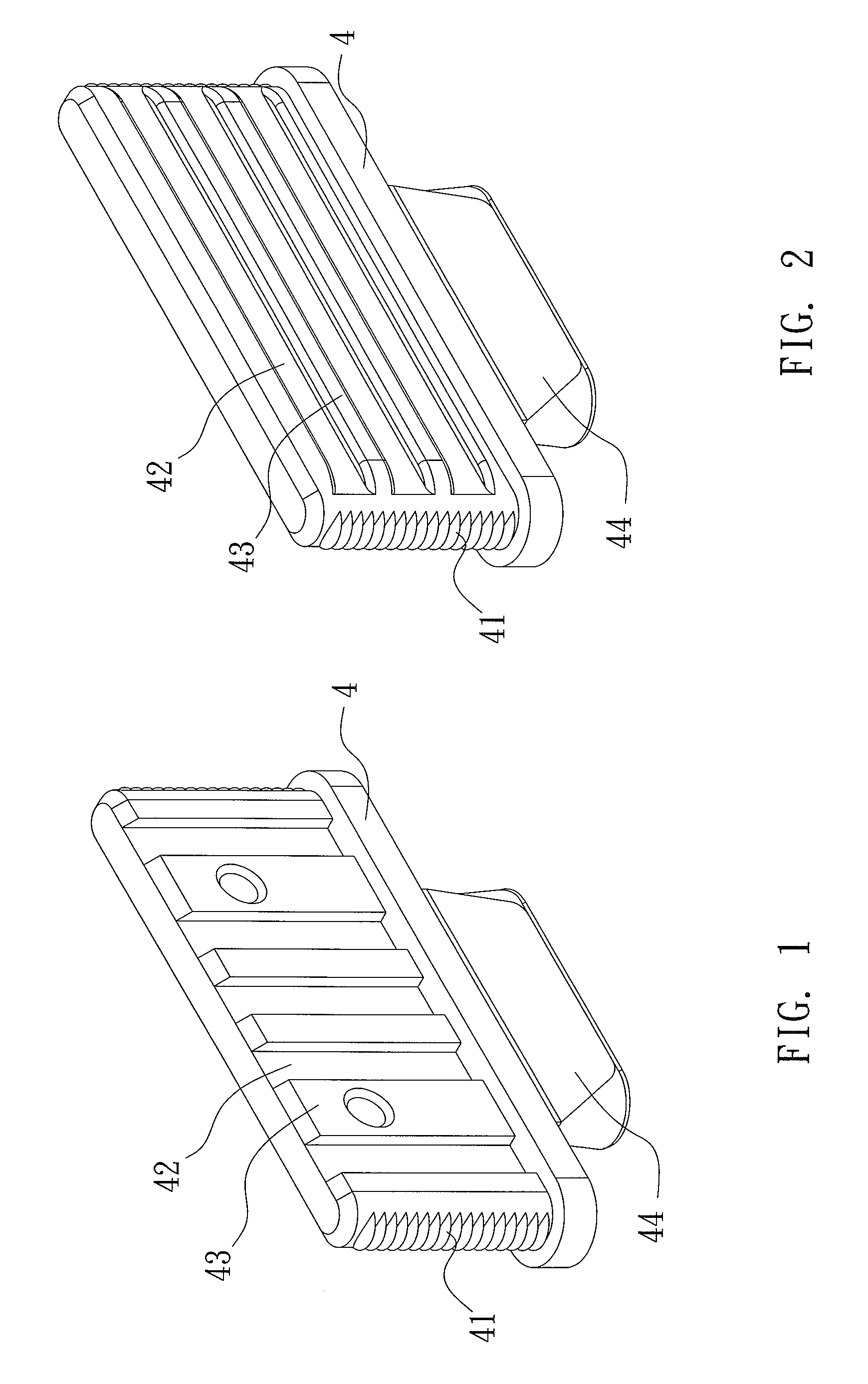
[0035]the fastening member 4 (as illustrated in FIGS. 1 and 2) having a plurality of wings 41 formed on two sides of an acting end thereof to engage with an inner wall of the second part 2, a number of recessed portions 42 mounted between front and rear sides thereof and spaced apart from each other, and a plurality of raised portions 43, each proximate t...

second embodiment

[0037]The fastening member 4 according to the present invention is retained to two grooves 33 of the retainer 3 (as shown in FIG. 10) and includes two supports 45 extending outward therefrom (as shown in FIGS. 8 and 9) and having a distance between the two supports 45.

[0038]In operation, the acting end of the fastening member 4 is fastened to the second parts 2 (as illustrated in FIG. 11), and the supports 45 of the fastening member 4 are fitted to the grooves 33 of the retainer 3. Thereafter, the second part 2 is pushed to troughs 33′ (as illustrated in FIG. 12) so that the supports 45 of the fastening member 4 are retained in the troughs 33′ securely.

third embodiment

[0039]The fastening member 4 according to the present invention is retained to grooves 34 of the retainer 3 (as shown in FIG. 15) and includes two L-shaped supports 46 extending outward therefrom (as shown in FIGS. 13 and 14) and having a L-shaped space between the two supports 46.

[0040]In operation, the acting end of the fastening member 4 is fastened to the second parts 2 (as illustrated in FIG. 16), and the supports 46 of the fastening member 4 are fitted to the grooves 34 of the retainer 3. Thereafter, the second part 2 is pushed to troughs 34′ (as illustrated in FIG. 17) so that the supports 46 of the fastening member 4 are retained in the troughs 34′ securely.

[0041]Besides, the fastening member 4 according to a fourth embodiment of the present invention includes a support 47 extending outward from one end thereof to be fitted to the groove 34″ of the retainer 3 as shown in FIG. 18, the support 47 has one laterally extended side parallel to the fastening member 4. The fastening...


PUM


Abstract

A retaining structure is used to retain a wooden first part with a wooden second part together and comprises a retainer fitted to a recess of the first part, and a fastening member to be engaged to the second part, wherein the fastening member has a plurality of wings formed on two sides of an acting end thereof, a number of recessed portions mounted between front and rear sides thereof and spaced apart from each other, and a plurality of raised portions; the recessed and raised portions are arranged longitudinally or horizontally between the front and rear sides of the acting end of the fastening member.

Description

BACKGROUND OF THE INVENTION[0001]1. Field of the Invention[0002]The present invention relates to a retaining structure that related parts of furniture and cabinet are fastened securely by using a retainer and a fastening member.[0003]2. Description of the Prior Art[0004]Related parts of convention wooden furniture or cabinet are fastened together by using different retaining methods. It is to be noted that a tenon is used to retain two adjacent parts together, or a recessed portion is formed on a wooden first part and a raised portion is arranged on a wooden second part so as to be engaged with each other, however such fastening methods can not retain related parts securely.[0005]The present invention has arisen to mitigate and / or obviate the afore-described disadvantages.SUMMARY OF THE INVENTION[0006]The primary object of the present invention is to provide a retaining structure that related parts of furniture and cabinet are fastened securely.[0007]Further object of the present in...

Claims


Application Information

Patent Timeline
IPC IPC(8): B27F1/00
CPCF16B12/125F16B12/22Y10T403/7094Y10T403/559Y10T403/7015F16B2200/30
Inventor LIU, MIN-SHENG
Owner LIU MIN SHENG
Why Eureka
Try Eureka