Electronic stethoscope

a technology of stethoscope and stethoscope, which is applied in the field of stethoscope, can solve problems such as limited performance, and achieve the effect of improving the auscultation sound

Inactive Publication Date: 2011-04-28
ALCATEL LUCENT SAS
View PDF7 Cites 50 Cited by
  • Summary
  • Abstract
  • Description
  • Claims
  • Application Information

AI Technical Summary

Benefits of technology

[0032]The stethoscope according to the invention benefits from an unlimited computation power for improving the auscultation sound heard by a physician, since the auscultation signal is sent, via the first link, to an auxiliary processing unit that has no limitation a priori; then the improved auscultation signal restituted by the auxiliary processing unit is sent to the local unit of the stethoscope, via the second link, and forwarded to the sound reproducing means, up to the ears of the physician.

Problems solved by technology

Known electronic stethoscopes provide some digital audio processing, but the performances are limited by the low computing power that can be embedded in an electronic stethoscope, and by the limited possibilities of the interface for controlling the functions of the stethoscope: It can only comprise a few switches and a very small display.

Method used


Image

  • Electronic stethoscope
  • Electronic stethoscope
  • Electronic stethoscope

Examples


first embodiment

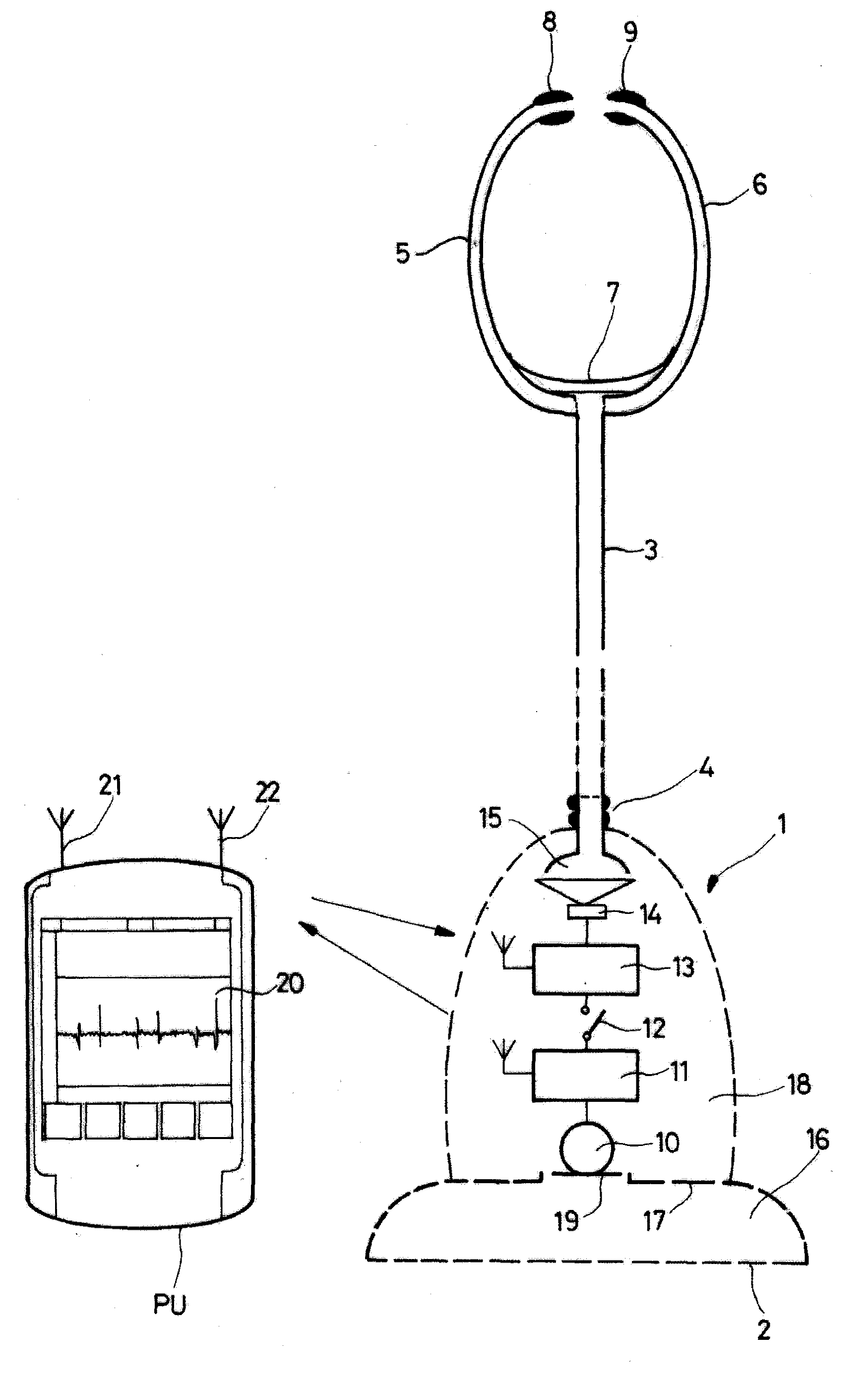
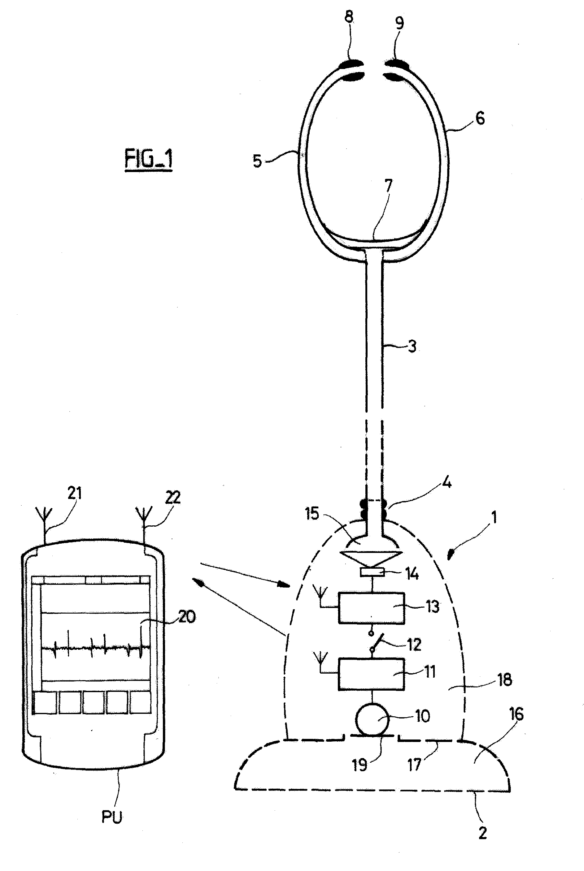
[0039]The first embodiment represented on FIG. 1 comprises a local unit 1-6 and an outer auxiliary processing unit PU that can be a few meters distant. The local unit 1-6 comprises:[0040]A chest piece 1 that is placed on the location where the user wants to hear sound. The chest piece 1 comprises a diaphragm 2 on the bottom side.[0041]A conventional flexible tube 3, attached to a ribbed stem 4 of the chest piece 1.[0042]A conventional headset made up of two metal eartubes 5, 6, a tension spring 7, and two eartips 8, 9.

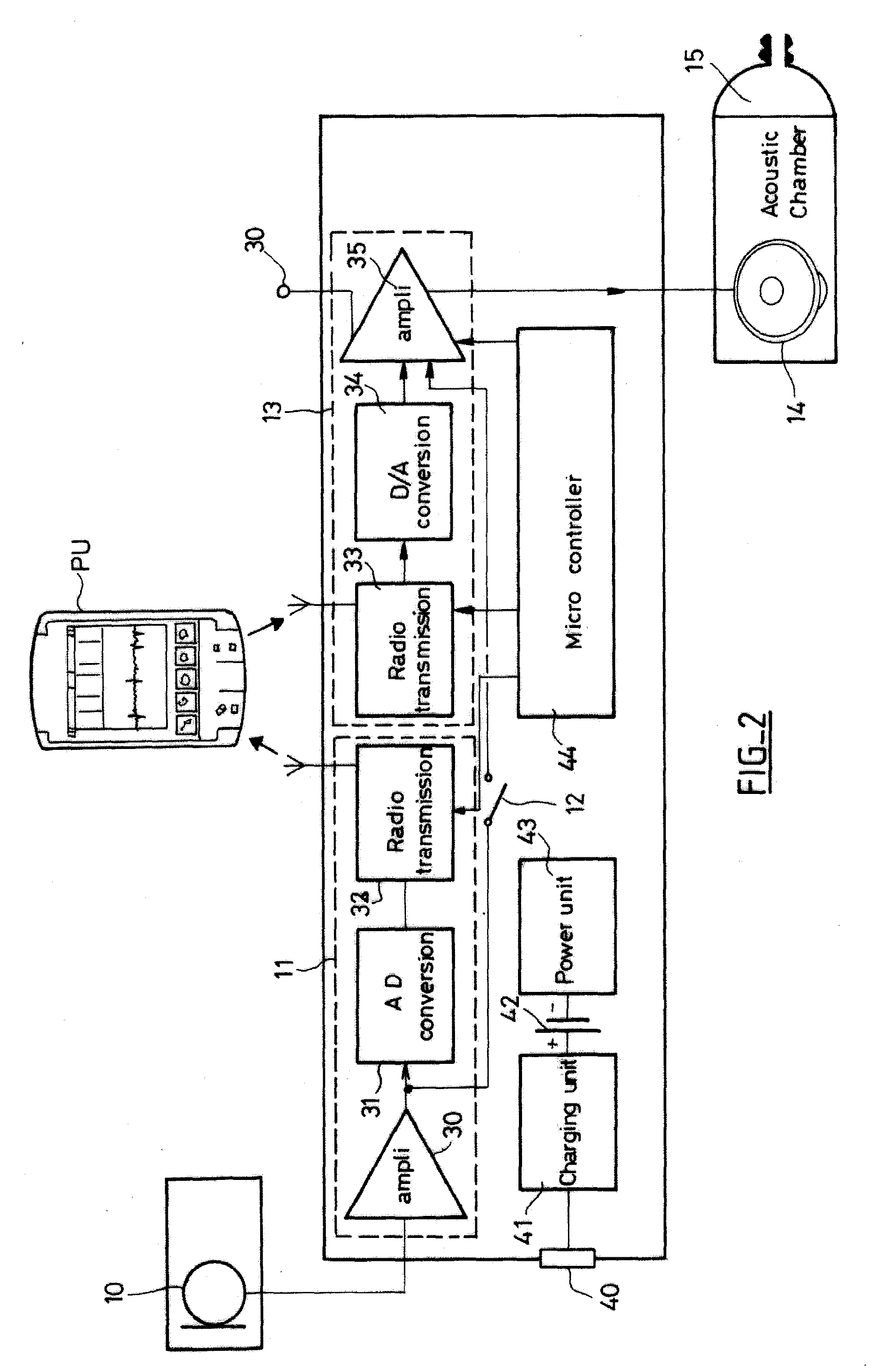
[0043]The chestpiece 1 comprises a cup shaped cavity 16 limited by the diaphragm 2 and by a metal wall 17 ; and a second cavity 18 containing an acoustical chamber 15, a loudspeaker 14, two electronic units 11-13, a switch 12, a microphone 10, and a battery not represented. The microphone 10 is placed in a hole 19 cut in the wall 17, for converting the sound transmitted by the diaphragm 2 into an electric signal.

[0044]A first electronic unit 11 amplifies the auscultati...

second embodiment

[0064]FIG. 3 shows a block diagram of the stethoscope according to the invention. This embodiment is designed to convert a classical stethoscope into an electronic one. A local unit 1′-6′ comprises a housing 1′ with an upper ribbed stem 4′ and a lower ribbed stem 4″. In this example, the classical stethoscope comprised:[0065]A chest piece qui comprises a diaphragm 54 on one side and a bell 53 on the other side.[0066]A conventional flexible tube 3, attached to a ribbed stem 52 of the chest piece.[0067]A conventional headset made up of two metal eartubes 5′, 6′, a tension spring 7′, and two eartips 8′, 9′.

[0068]The user has converted it into an electronic stethoscope by:[0069]Cutting the tube 3 into two segments 3′ and 3″,[0070]Then attaching the segment 3′ to the upper ribbed stem 4′ of the housing 1′,[0071]And the segment 3″to the lower ribbed stem 4″ of the housing 1′.

[0072]The lower ribbed stem 4″ continues into the housing 1′ by a first acoustical chamber 51 containing a micropho...


PUM


Abstract

An electronic stethoscope comprises a local unit (1-6) and an outer auxiliary processing unit (PU). The local unit (1-6) comprises:—a microphone (10),—first coupling means (11) that can receive an auscultation signal supplied by the microphone (10), and transmit it to the auxiliary processing unit (PU), on a first link,—second coupling means (13) that can receive an audio signal, from the auxiliary processing unit (PU), on a second link,—and sound reproducing means (14), for reproducing an audio signal supplied by the second coupling means (13); The auxiliary processing unit (PU) comprises:—receiving means (21) that can receive an auscultation signal from a local unit (1-6), on a first link,—processing means for processing an auscultation signal received by the receiving means, and restituting an improved auscultation signal;—and transmitting means (22) that can send the improved auscultation signal to a local unit (1-6), on the second link

Description

BACKGROUND OF THE INVENTION[0001]1. Field of the Invention[0002]The invention relates to an electronic stethoscope of the type comprising a microphone, electronic sound processing means, and sound reproducing means, such as a loudspeaker or headphones. Stethoscopes are used by physicians to listen to sounds from the organism, in particular heart and lungs. An electronic stethoscope gives the possibility of active amplification and filtering to any desired degree. Furthermore there is a possibility to permit physicians to discuss the same phenomenon during simultaneous auscultation, as several headphones may well be connected to one and the same amplifier with filter.[0003]2. Description of the Prior Art[0004]A known construction of an electronic stethoscope is described in U.S. Pat. No. 6,134,331. It comprises: a microphone, a preamplifier, a first amplifier, a digital filtering unit, and a second amplifier coupled to an output.[0005]The preamplifier performs impedance conversion. A...

Claims


Application Information

Patent Timeline
Patent Type & Authority Applications(United States)
IPC IPC(8): A61B7/04
CPCA61B5/002A61B7/04
Inventor GASS, RAYMOND
Owner ALCATEL LUCENT SAS
Why Eureka
Try Eureka