
Partial Face Detector Red-Eye Filter Method and Apparatus

a filter and partial face technology, applied in the field of flash photography, can solve the problems of objectionable phenomenon, less than desirable position, and 0.2 to 0.6 seconds before flash

Inactive Publication Date: 2011-05-05
TESSERA TECH IRELAND LTD
View PDF103 Cites 33 Cited by
  • Summary
  • Abstract
  • Description
  • Claims
  • Application Information

AI Technical Summary

Problems solved by technology

This objectionable phenomenon is well understood to be caused in part by a small angle between the flash of the camera and the lens of the camera.
Unfortunately, the pre-flash is an objectionable 0.2 to 0.6 seconds prior to the flash photograph.
Consequently the subject may believe the pre-flash is the actual photograph and be in a less than desirable position at the time of the actual photograph.

Method used


Image

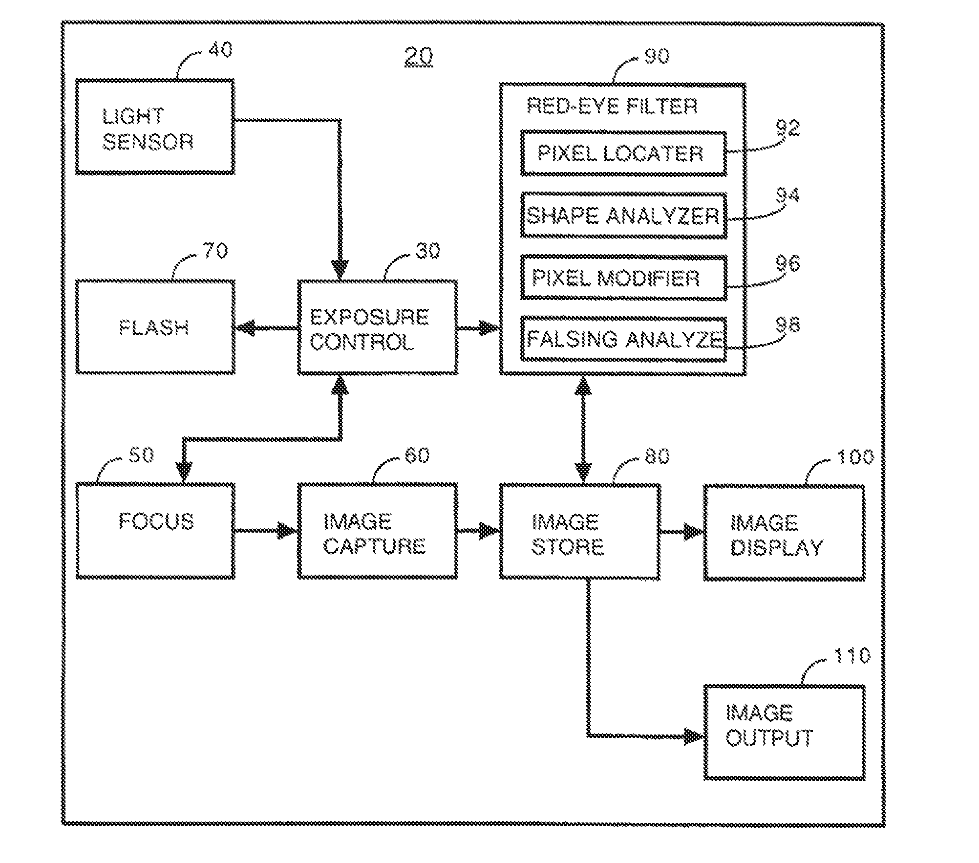
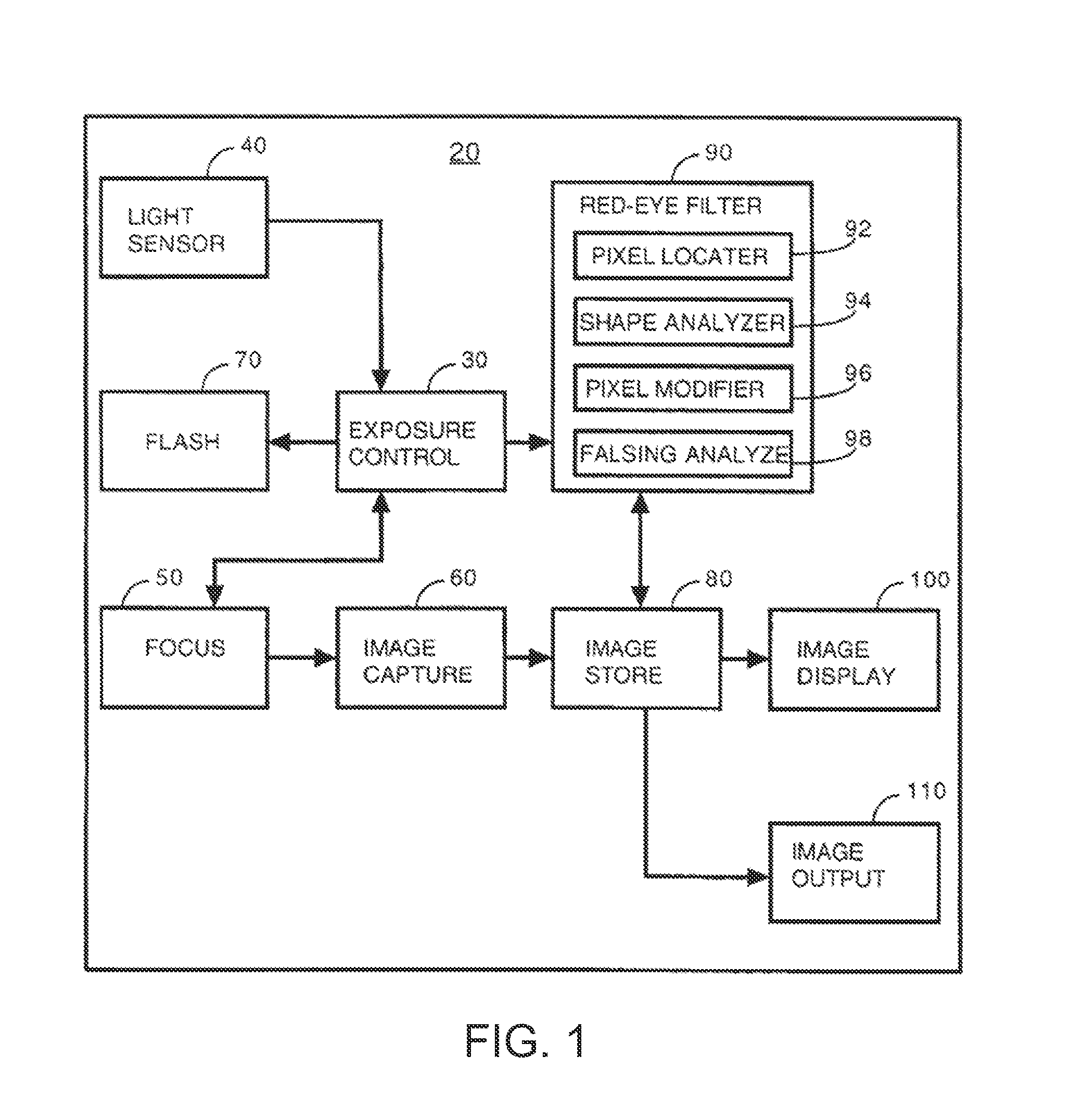
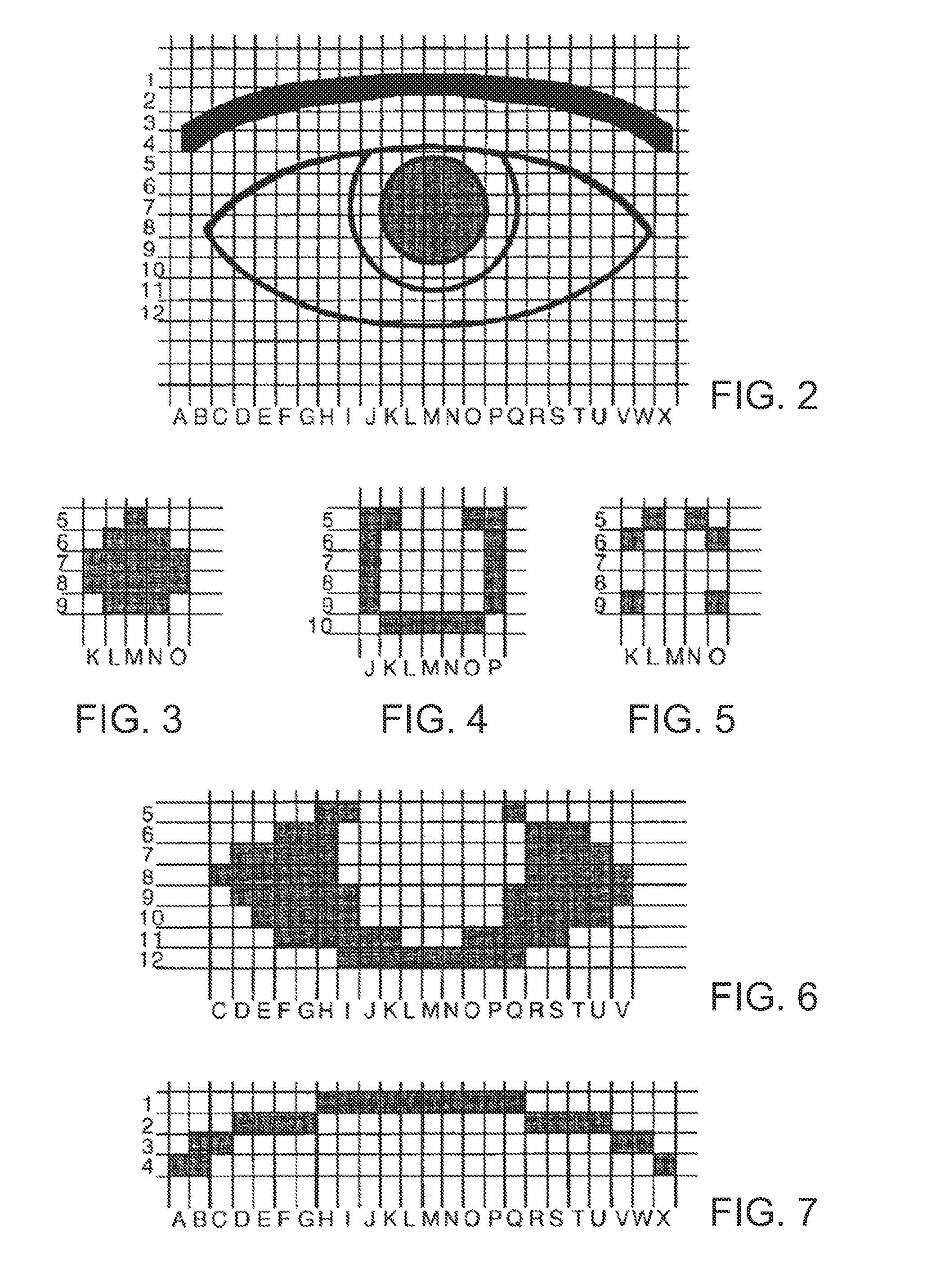
  • Partial Face Detector Red-Eye Filter Method and Apparatus
  • Partial Face Detector Red-Eye Filter Method and Apparatus
  • Partial Face Detector Red-Eye Filter Method and Apparatus

Examples


example process

[0099]In an exemplary process, a redeye detection algorithm may be applied on an entire image, which may be a low resolution image such as a preview or postview image. A red eye list may be obtained of regions suspected as candidate red eye regions. An extended eye detector may be applied to the image from which an extended eyes list is generated. Using one or more geometric operations, such as applying rectangles or other polygons or elliptical shapes to the image, a list is generated from the extended eyes list.

[0100]Redeye detection accuracy improvement is achieved when the red eye candidate region list is combined with the extended eyes list or the list discussed above as being generated therefrom by applying one or more geometric operations. Each eye- or eye pair-rectangle may be verified by intersecting the redeye candidate list. If not, a new refined red eye detection may be applied inside the eye- or eye pair-rectangle, e.g., based on the presence of the eye- or eye pair-rec...

example method

[0215]FIG. 21 is a flow chart showing a method according to certain embodiments. The segmentation filter 2090 of the image acquisition device 2020 (also referred to as a “camera” in parts of the disclosure) shown in FIG. 20 can use the foreground / background segmentation information 2099 of a stored image I(x,y) to produce a binary map with foreground (FG) pixels and background (BG) pixels (Block 2210). The binary map might, for example, assign a first value to background pixels and a second value to foreground pixels such that an image corresponding to the binary map shows the foreground image in black and the background in white. U.S. Patent Publication No. 2006 / 0039690, titled “Foreground / Background Segmentation In Digital Images With Differential Exposure Calculations,” filed Aug. 30, 2005, is hereby incorporated by reference in its entirety. In one embodiment, the binary map is refined to improve the quality of the segmentation of a foreground object from the background of a dig...


PUM


Abstract

A digital camera has an integral flash and stores and displays a digital image. Under certain conditions, a flash photograph taken with the camera may result in a red-eye phenomenon due to a reflection within an eye of a subject of the photograph. A digital apparatus has a red-eye filter which analyzes at least one partial face region identified within the digital image for the red-eye phenomenon and modifies the image to eliminate the red-eye phenomenon by changing the red area to black. The modification of the image is enabled when a photograph is taken under conditions indicative of the red-eye phenomenon. The modification is subject to anti-falsing analysis which further examines the area around the red-eye area for indicia of the eye of the subject. The detection and correction can be optimized for performance and quality by operating on subsample versions of the image when appropriate.

Description

RELATED APPLICATIONS[0001]This application is a continuation of U.S. patent application Ser. No. 12 / 551,282, filed Aug. 31, 2009, published as US20100053362, which claims the benefit of priority to U.S. provisional patent application Ser. Nos. 61 / 094,034, filed Sep. 3, 2008 and 61 / 182,625, filed May 29, 2009 and 61 / 221,455, filed Jun. 29, 2009, and which is a continuation-in-part (CIP) of U.S. Ser. No. 12 / 035,416, filed Feb. 21, 2008, published as US20080186389, which is a continuation of U.S. Ser. No. 10 / 772,767, filed Feb. 4, 2004, now U.S. Pat. No. 7,352,394.FIELD OF THE INVENTION[0002]The invention relates generally to the area of flash photography, and more specifically to filtering “red-eye” from a digital camera image.BACKGROUND OF THE INVENTION[0003]“Red-eye” is a phenomenon in flash photography where a flash is reflected within a subject's eye and appears in a photograph as a red dot where the black pupil of the subject's eye would normally appear. The unnatural glowing red...

Claims


Application Information

Patent Timeline
Patent Type & Authority Applications(United States)
IPC IPC(8): H04N5/217H04N5/228H04N23/40
CPCG06K9/00248G06K9/0061G06K9/4614G06T7/408G06T2207/10024H04N1/62H04N1/624H04N5/2354G06T5/005G06T2207/30216G06T7/90G06V40/165G06V40/193G06V10/446H04N23/74G06T5/77
Inventor NANU, FLORINSTEINBERG, ERANCORCORAN, PETERPOSOSIN, ALEXEIBIGIOI, PETRONELDRIMBAREAN, ALEXANDRUPETRESCU, STEFANGANGEA, MIHNEACAPATA, ADRIANCIUC, MIHAIZAMFIR, ADRIAN
Owner TESSERA TECH IRELAND LTD
Learn More